For starters, this is just a technical reference to assist other while installing aftermarket suspension on a Z33 chassis. Neither NICOclub, nor myself, are to be held responsible for any damage to your vehicle or any injury to yourself that may occur while installing aftermarket suspension with reference to this writeup.
On a lighter note, I will be doing my best to provide the information needed to install Raceland height adjustable coilovers on a Nissan 350Z.
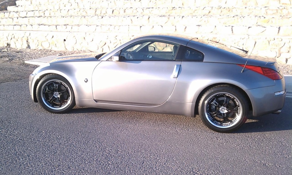
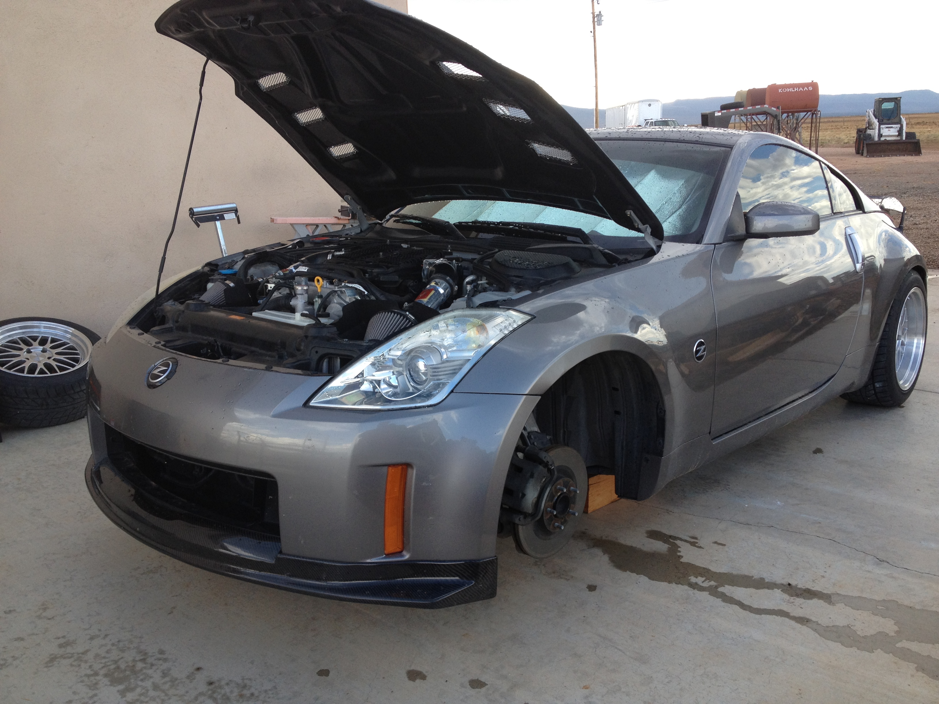
I purchased this 350Z in the middle of 2012 to use it as a more comfortable/reliable daily driver than my old Z32. Since then I’ve been performing minor visual and performance modifications to the Z, slowly getting closer to the Z I’ve seen in my mind for quite some time now. After many different carbon fiber pieces, some pretty okay wheels, and a couple interior modifications, the time has come install a set of coilovers!!
With a fairly tight budget, and other projects on hand, Raceland’s strangely affordable coilovers caught my eye.
These coilovers, while not intended for track use, seem to be a perfect candidate to drop the stance of my daily without taking too big of a hit at the bank. At just $469 a set, I figured I could use the extra money saved for supporting modifications to correct the alignment after the drop. Raceland also offers a two year warranty on their coilovers, and great customer service.
These Raceland 350Z coilovers ONLY offer height adjustability. They DO NOT have any adjustment for damping front or rear, nor do they have camber adjustment for the front. Because these do not offer camber adjustability in front, I also installed aftermarket front upper A-arms for camber adjustment, as there is no camber adjustment stock. For the rear I installed camber arms, and toe bolts with larger offset cam washers for more toe adjust-ability to help align everything after the drop.
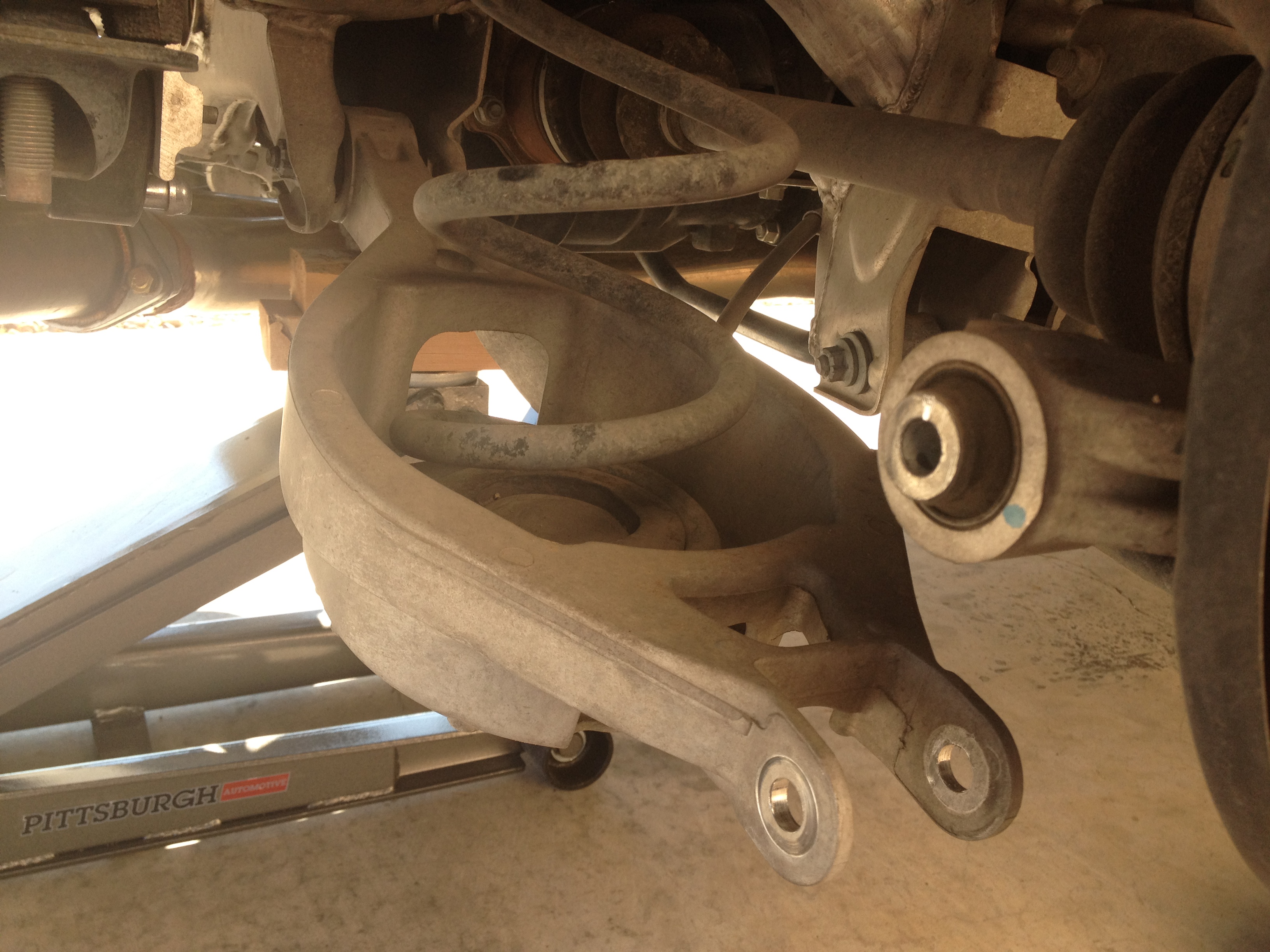
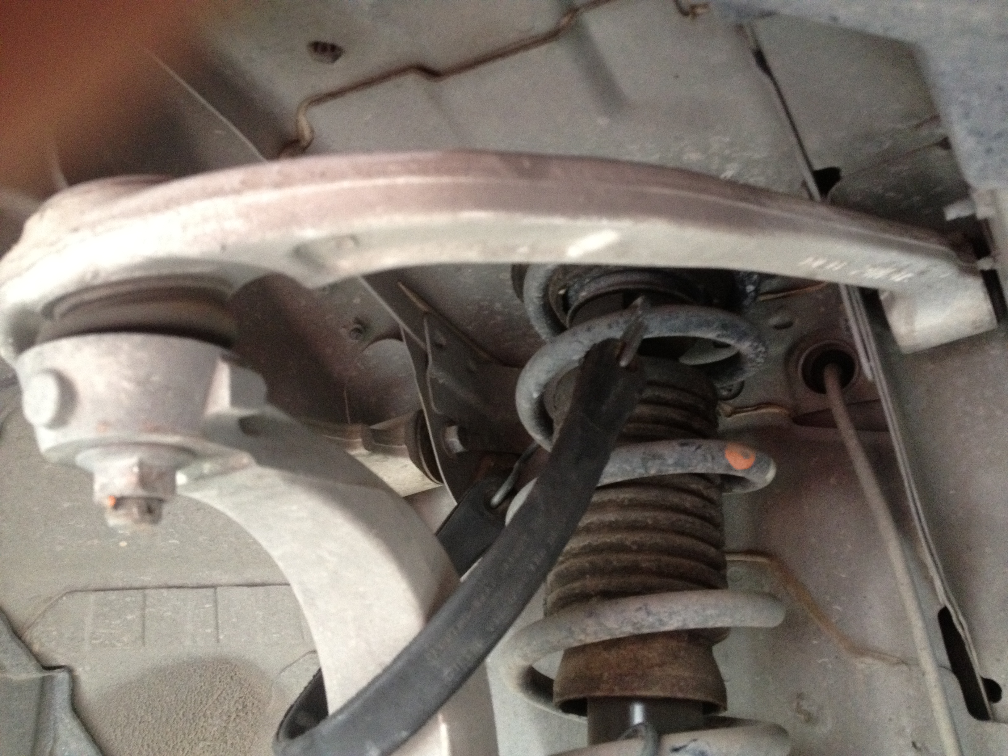
I started on the rear. Jack up the car by the rear diff housing, and support the vehicle with jack stands on either side. It’s not a bad idea to also leave the jack underneath the vehicle with just enough load to keep it from moving for added safety. After removing the wheels, you’ll see the shock that is separate from the spring that is located in the lower control arm bucket.
To remove the spring, I started by removing the 17mm nut and bolt connecting the lower control arm to the knuckle, then I loosened the stock toe bolt/nut located on the innermost mount of the lower control arm (LCA). The bolt is 17mm and the nut is 19mm. After loosening the toe bolts, the LCA should be more maneuverable, and allow you to push down enough to remove the spring assembly.
You will not have any use for the stock rear springs and rubber pieces as the Raceland units use a “true” coilover design in the rear combining the shock and spring into a single unit. This also allows you to use aftermarket adjustable lower control arms if it suits your specific build/budget.
After the spring is removed, I also removed the stock camber arm by removing the 17mm nut and bolts on the knuckle end and the 17mm bolt, and 19mm nut on the innermost end of the camber arm. I only removed this arm completely to replace it with aftermarket adjustable units.
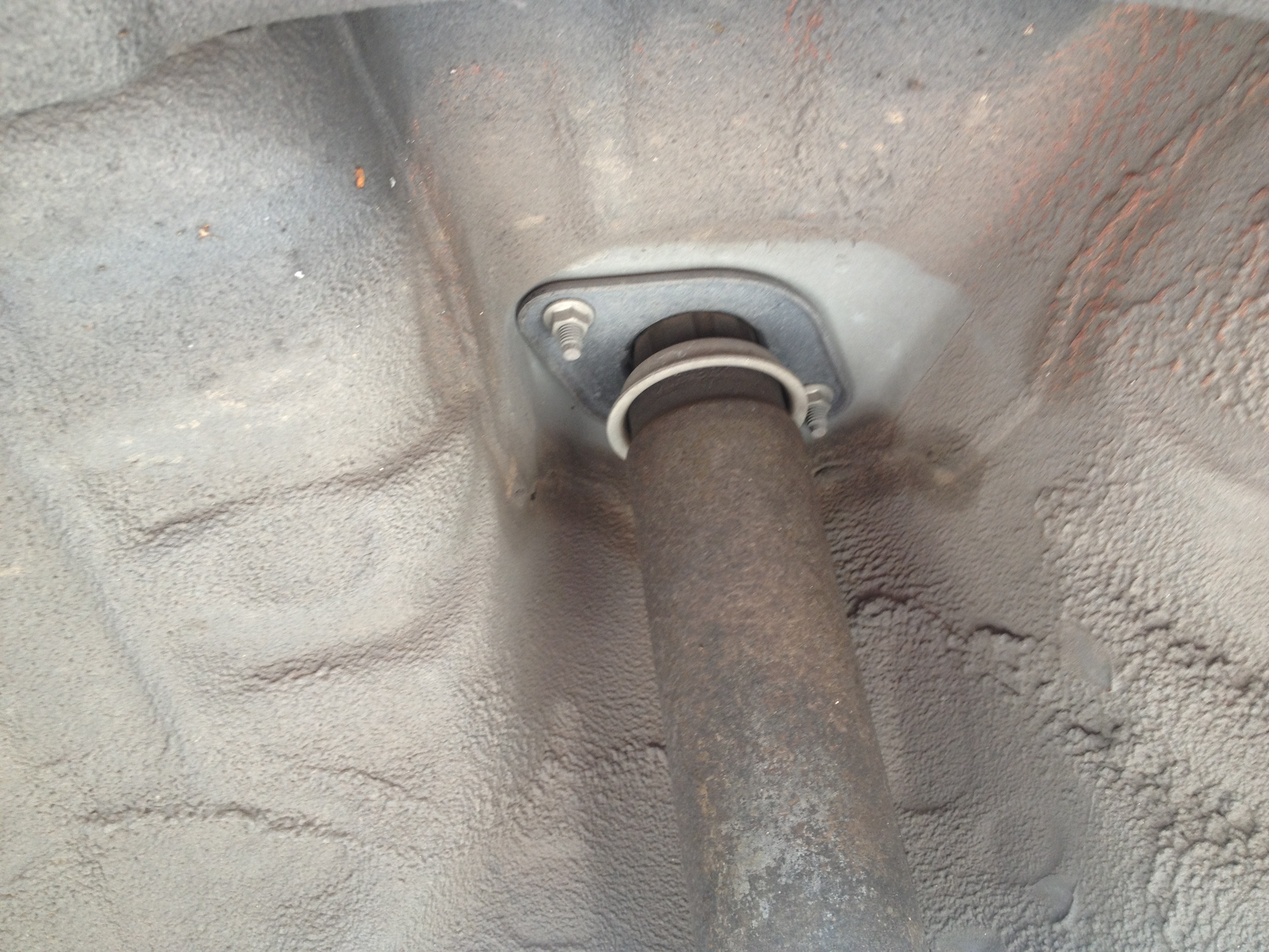
Finally I removed the 17mm lower bolt on the lower mount of the shock followed by the two 12mm nuts securing the top mount of the shock to the strut tower.
After removing the nuts and bolt connecting the shock, push down on the knuckle enough to allow you to maneuver the rear shock (top end first) out of the wheel well.
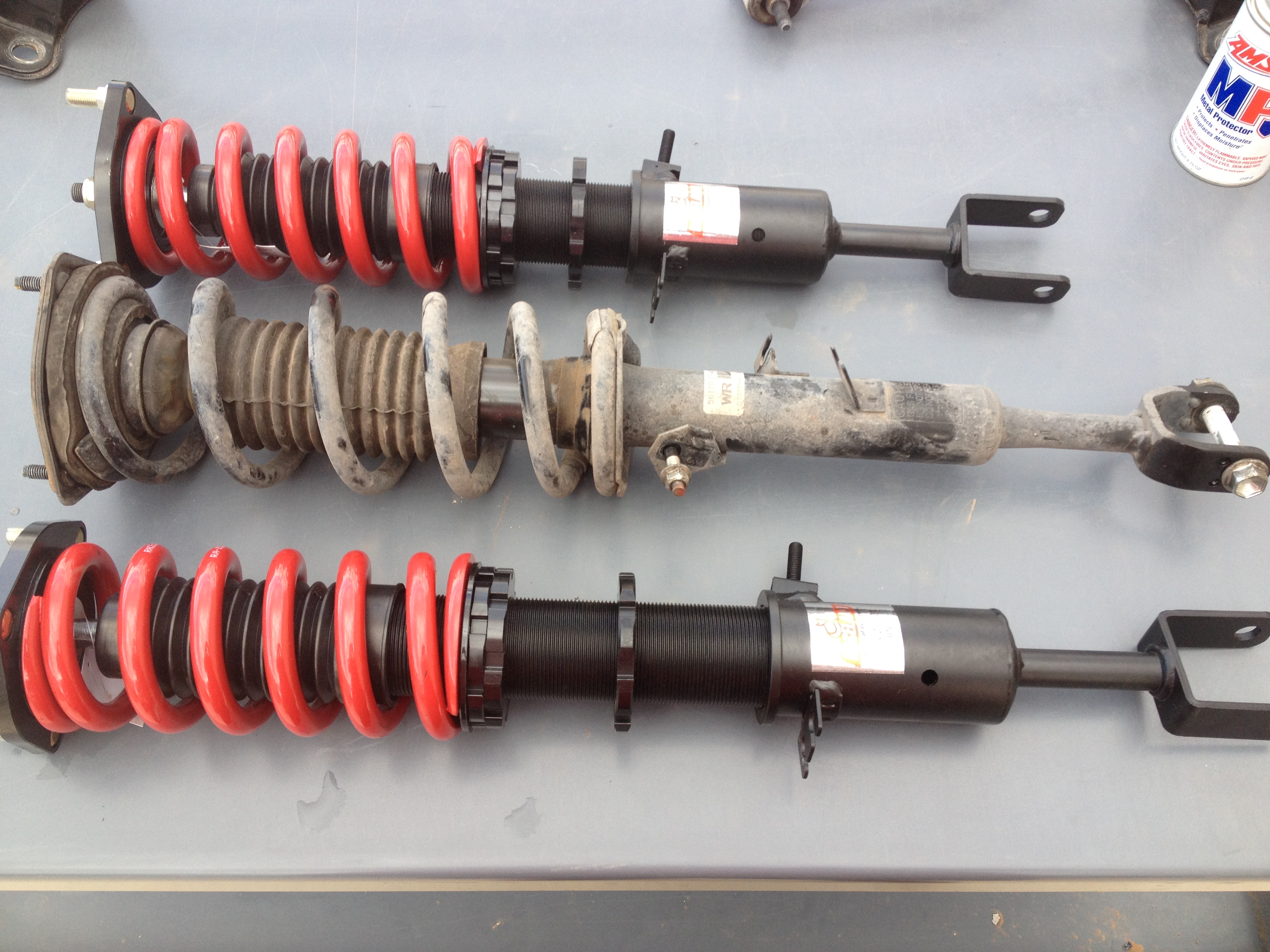
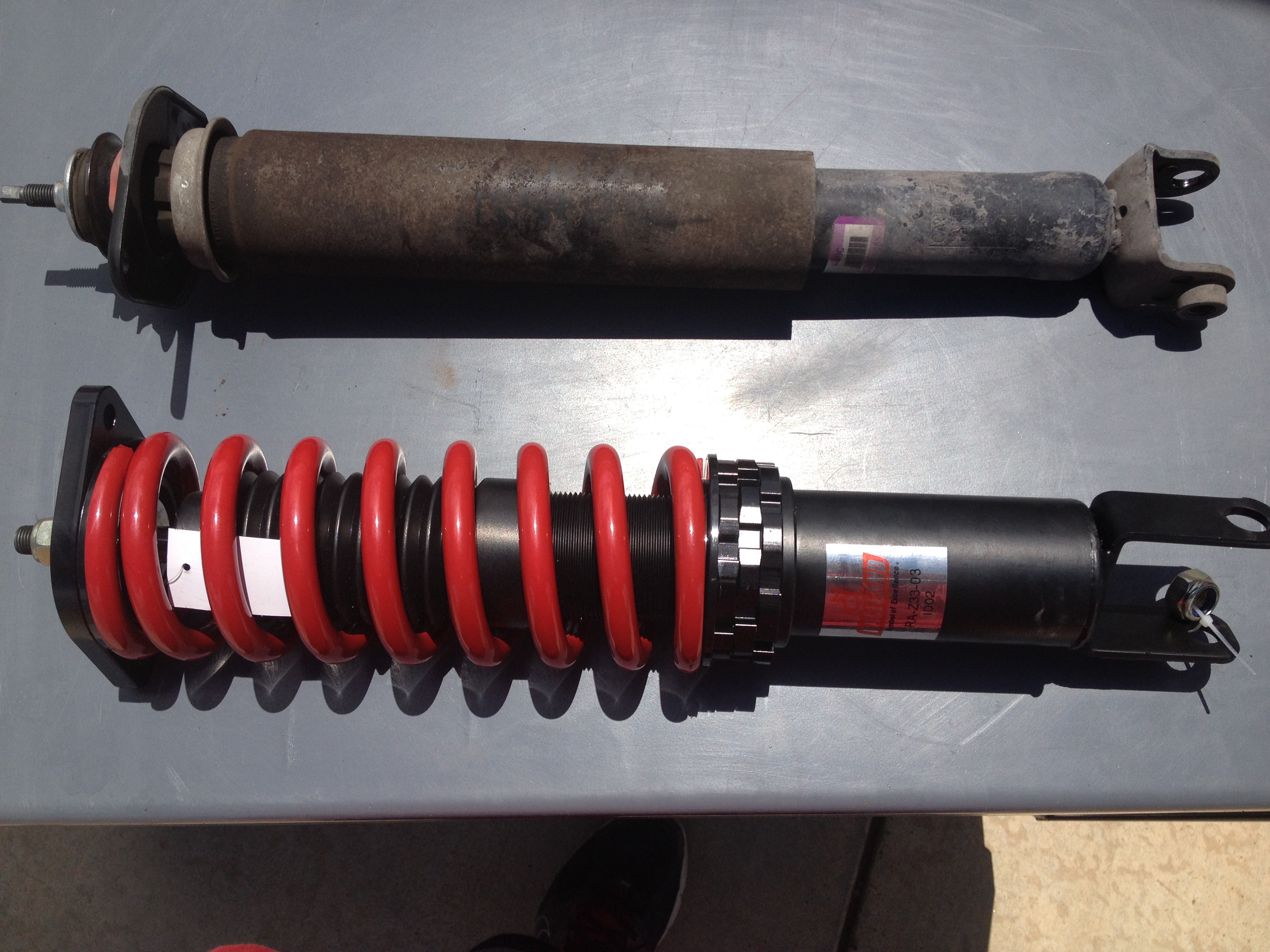
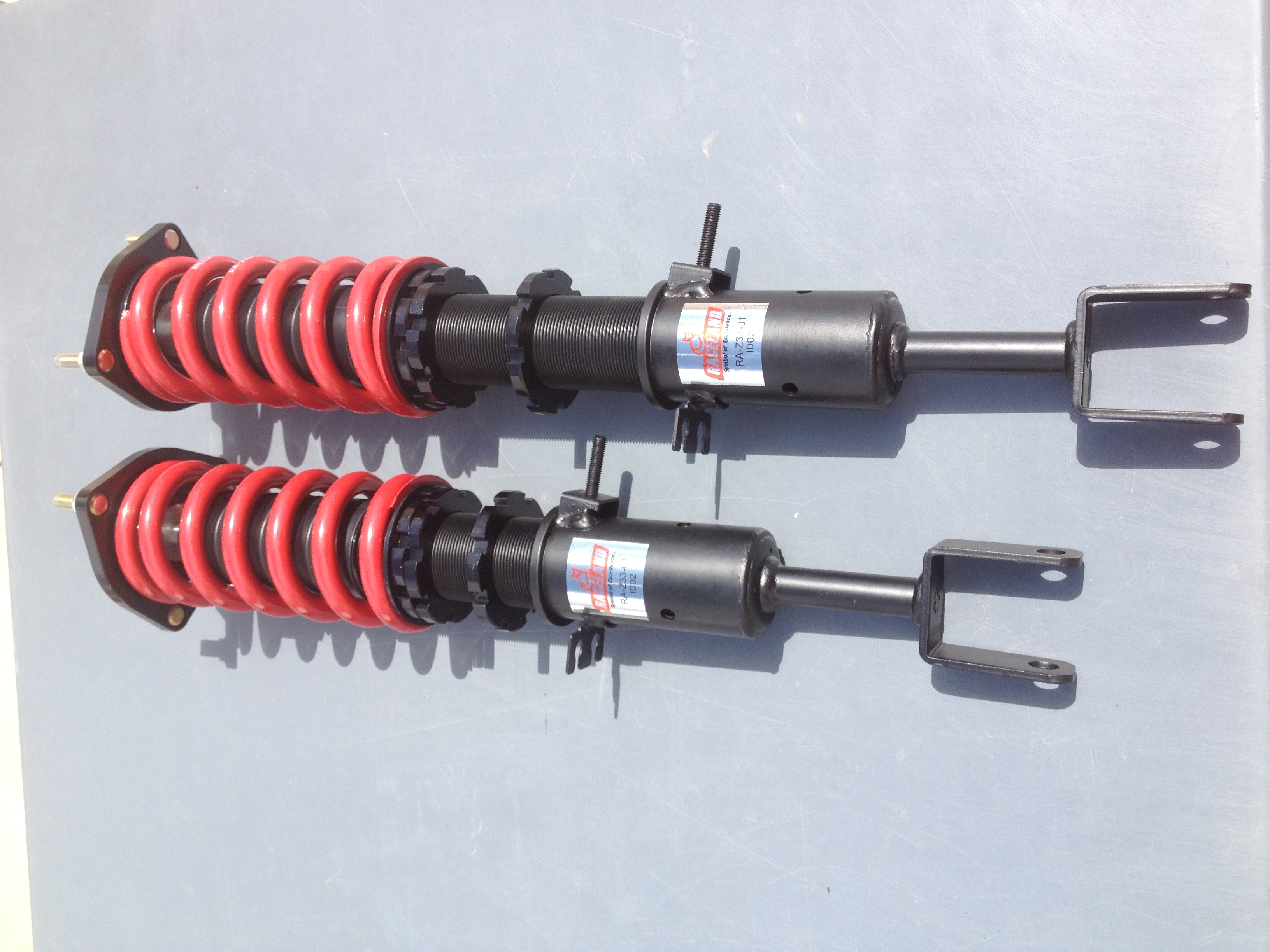
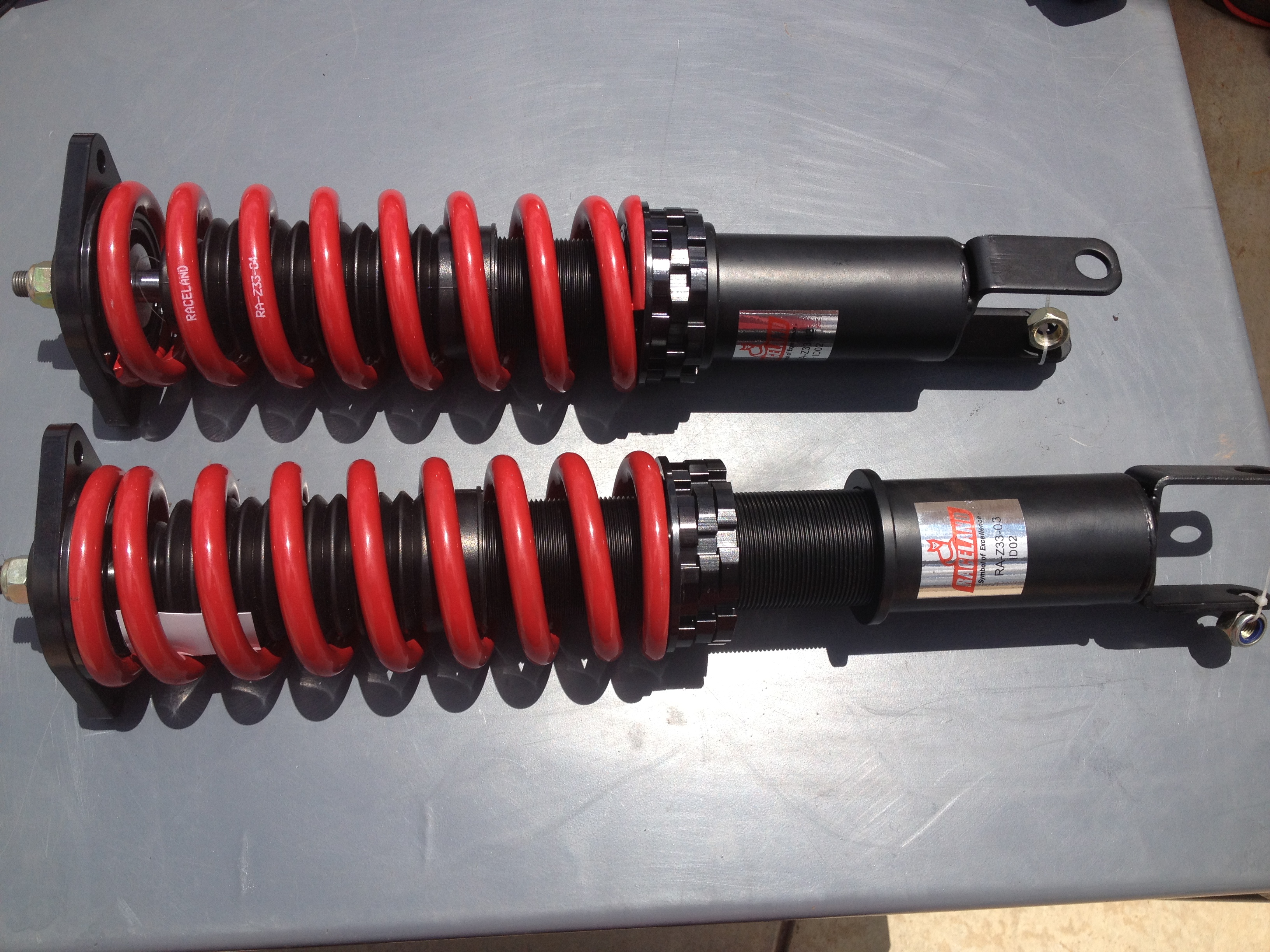
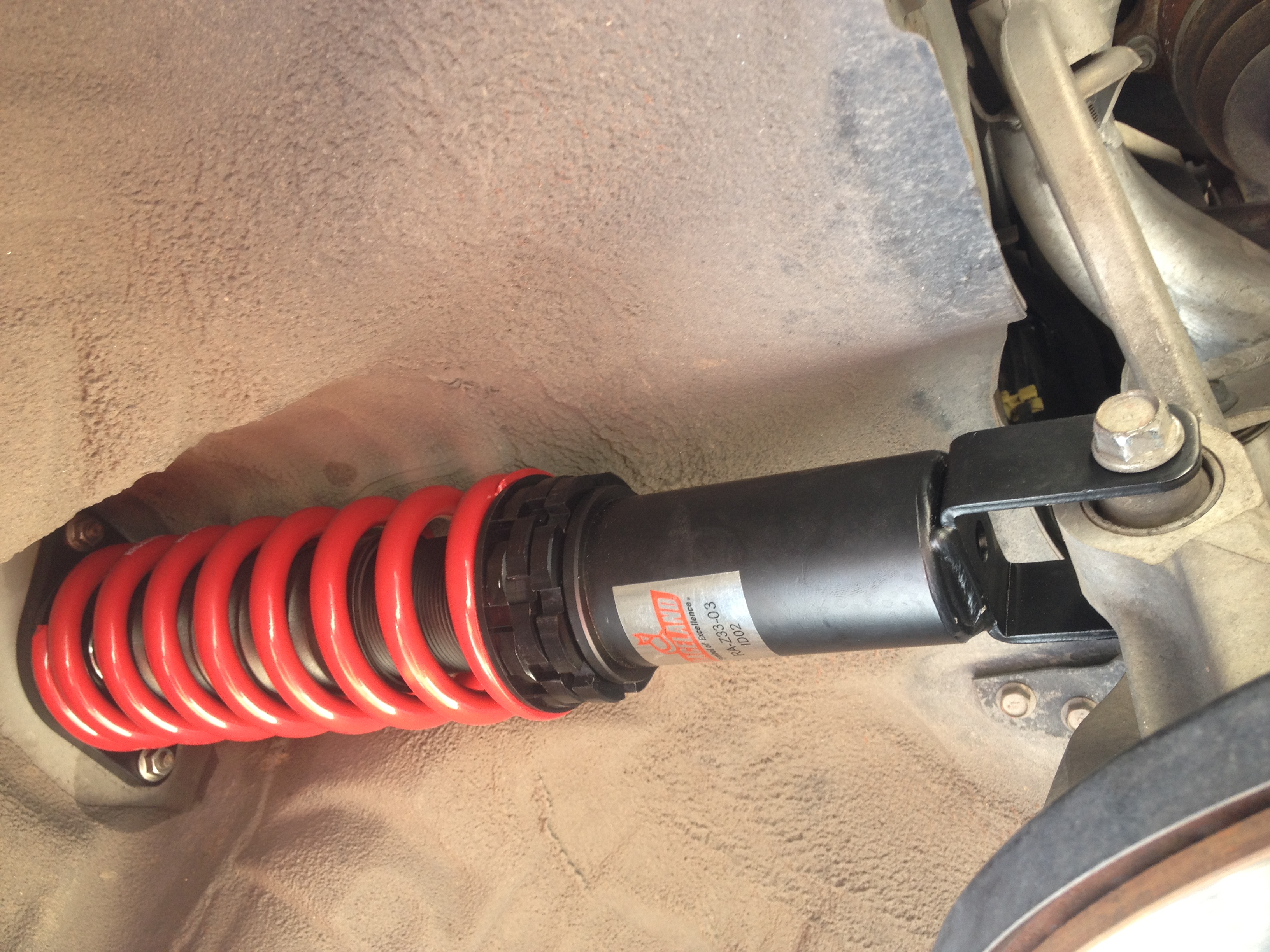
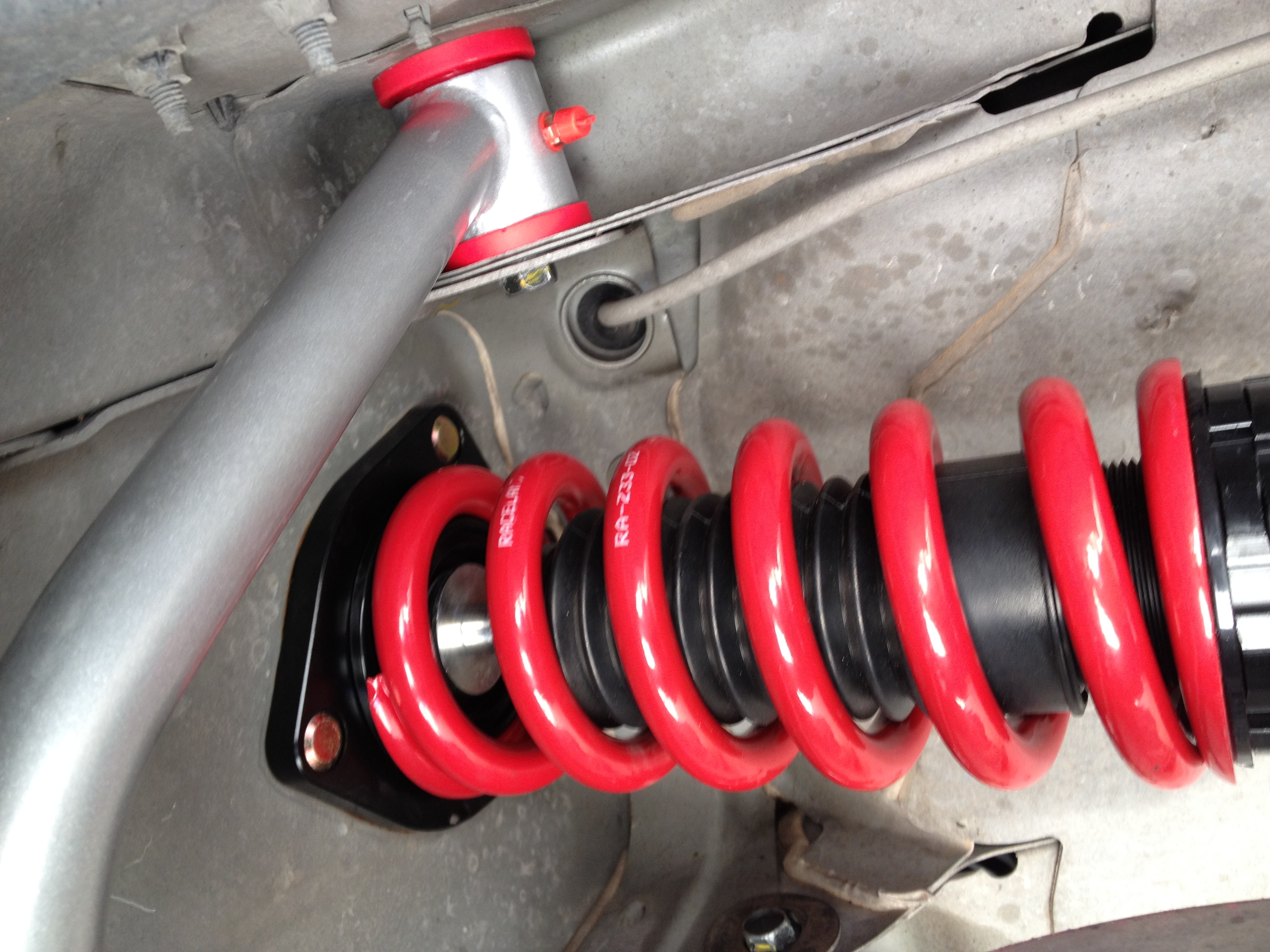
Here are some pictures of the coilovers as compared to the stock units, as well as the range of adjustment front and rear.
As you can see, there is a good three inches of height adjustment to play with in the front as well as the rear.
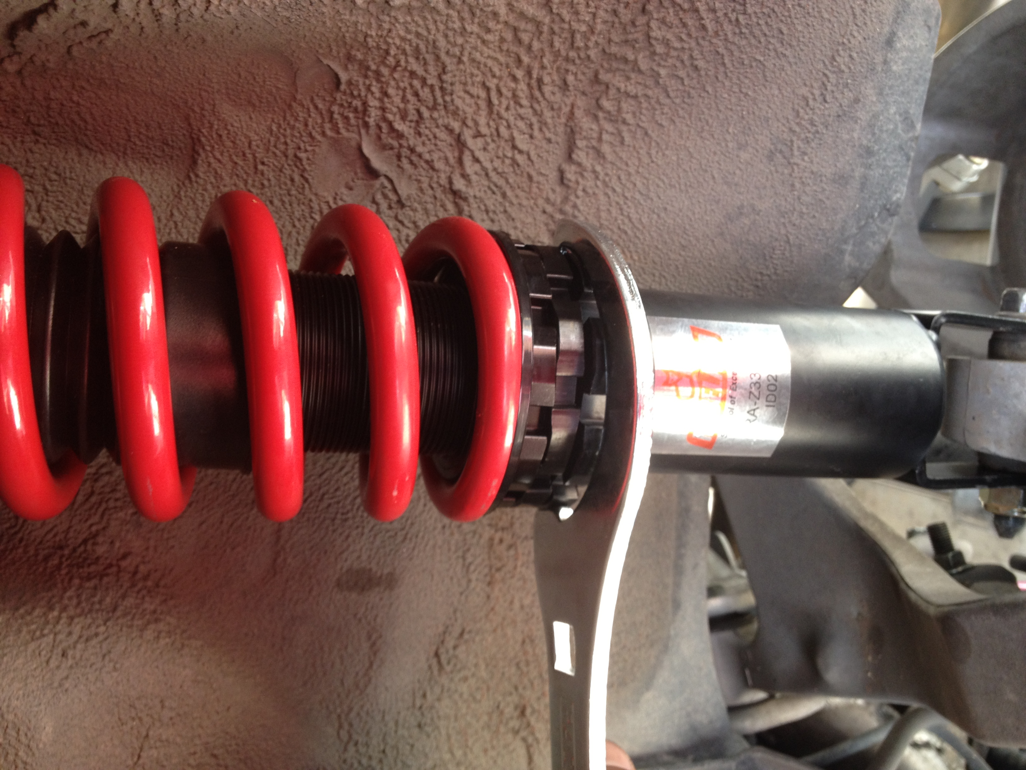
These coilovers are adjusted by way of loosening the lower locking perch, and threading the lower mount up, or down along the main body of the shock. You can also adjust preload on the springs by adjusting the two perches underneath the spring.
Raceland recommends that you do not surpass 5mm of preload to prevent premature wear on the pillowball mounts.
To set preload, I followed the recommendations found in NICO’s s13 Raceland install, and adjusted the spring perches until the spring moved up and down, then re-tighten the perch until there is no more up and down movement but, you are still able to twist the spring side to side. After setting spring preload, tighten the upper locking perch to the perch preloading the spring, and you are ready to determine your preferred ride height!!
The lower mounts front and rear have almost exactly two inches of threads inside, so I assume (to be safe) that maximum height is having a minumum of the two inches of threads secured to the main body of the coilover. For the lowest setting, I completely bottomed out the lower mounts on the fronts, and threaded up the lower mount of the rears as far as I could without having to move the perches up higher, setting too much preload on the springs.
After setting your preferred ride height, head back into the fender well with coilover, lower mount first, and install the lower mount with the original 17mm bolt, and the supplied 19mm nut. After getting the lower mount bolted on you can re-install the lower control arm, and camber arm, and procede to jack up on the assembly from the lower control arm while lining up the upper mount with the two studs up top. Once you get the coilover all the way up, you can now re-install the two upper 12mm nuts. Be sure to use the supplied perch wrenches to tighten locking perches.
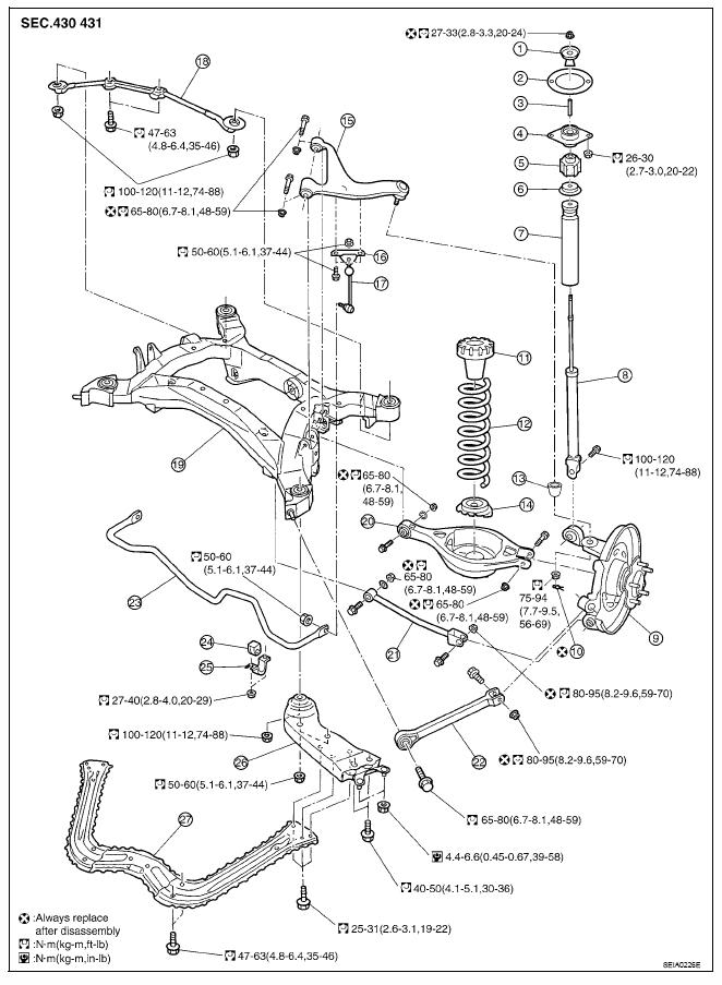
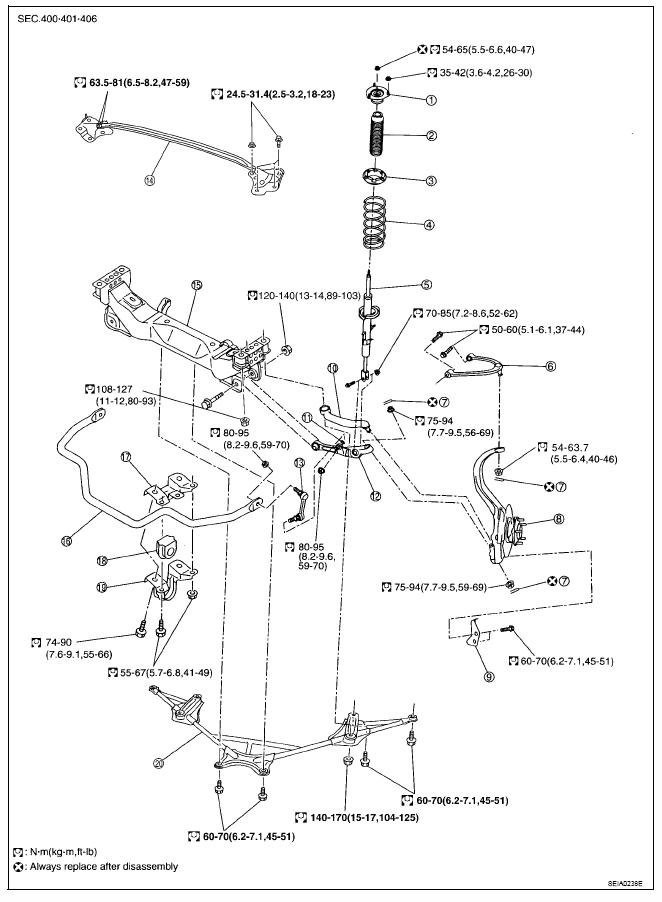
Preload the suspension by lifting the assembly by the lca with a jack, and torque everything to the recommended specifications. I used this diagram for torque specs-
Be sure to double check the torque of every nut and bolt dealt with.
Repeat on the other side, and you’re done with the rear coilover installation.
Put your wheels back on, and lower the rear of the vehicle back onto the floor.
ON TO THE FRONT!!
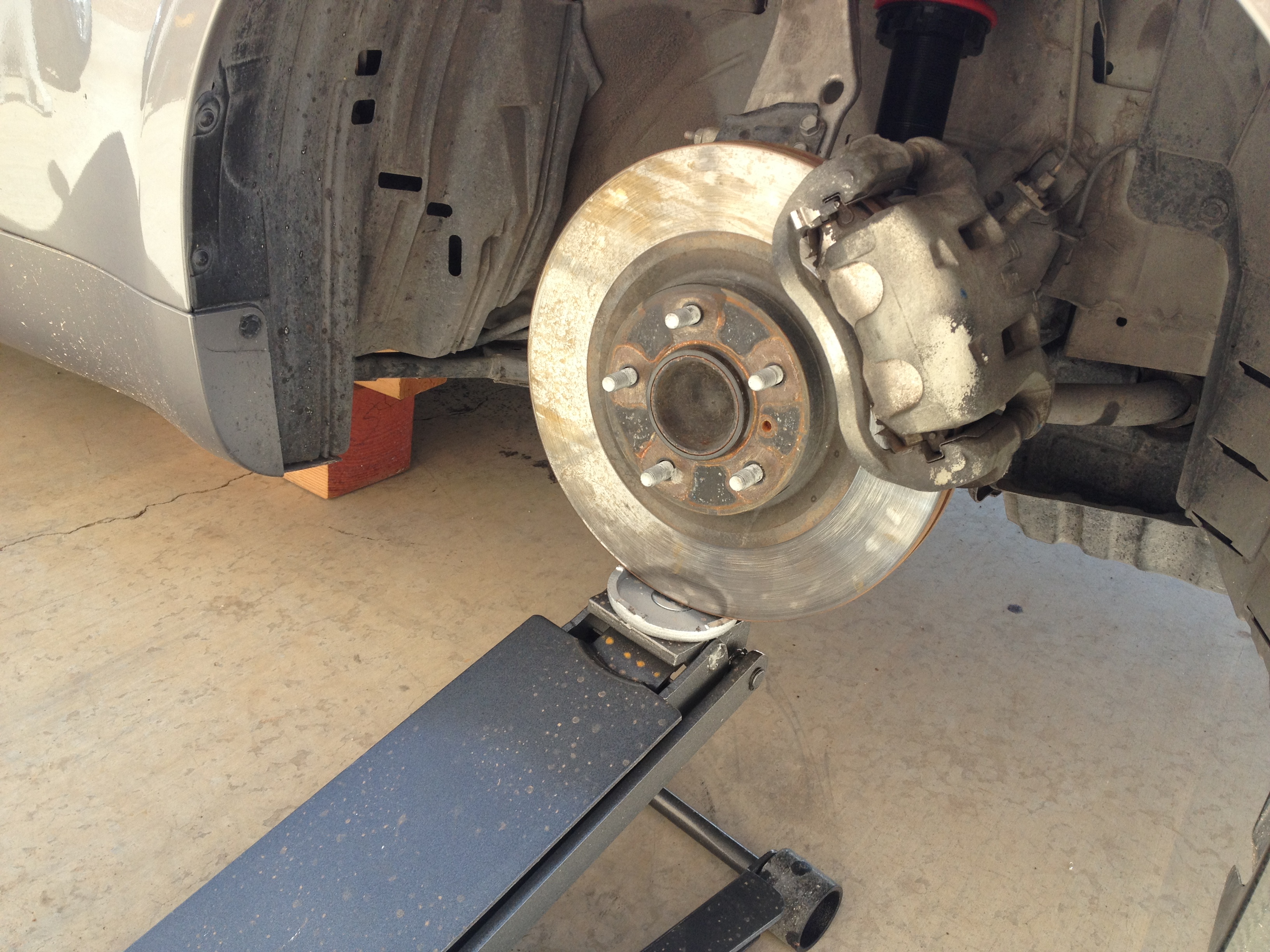
Jack up the front and support vehicle.
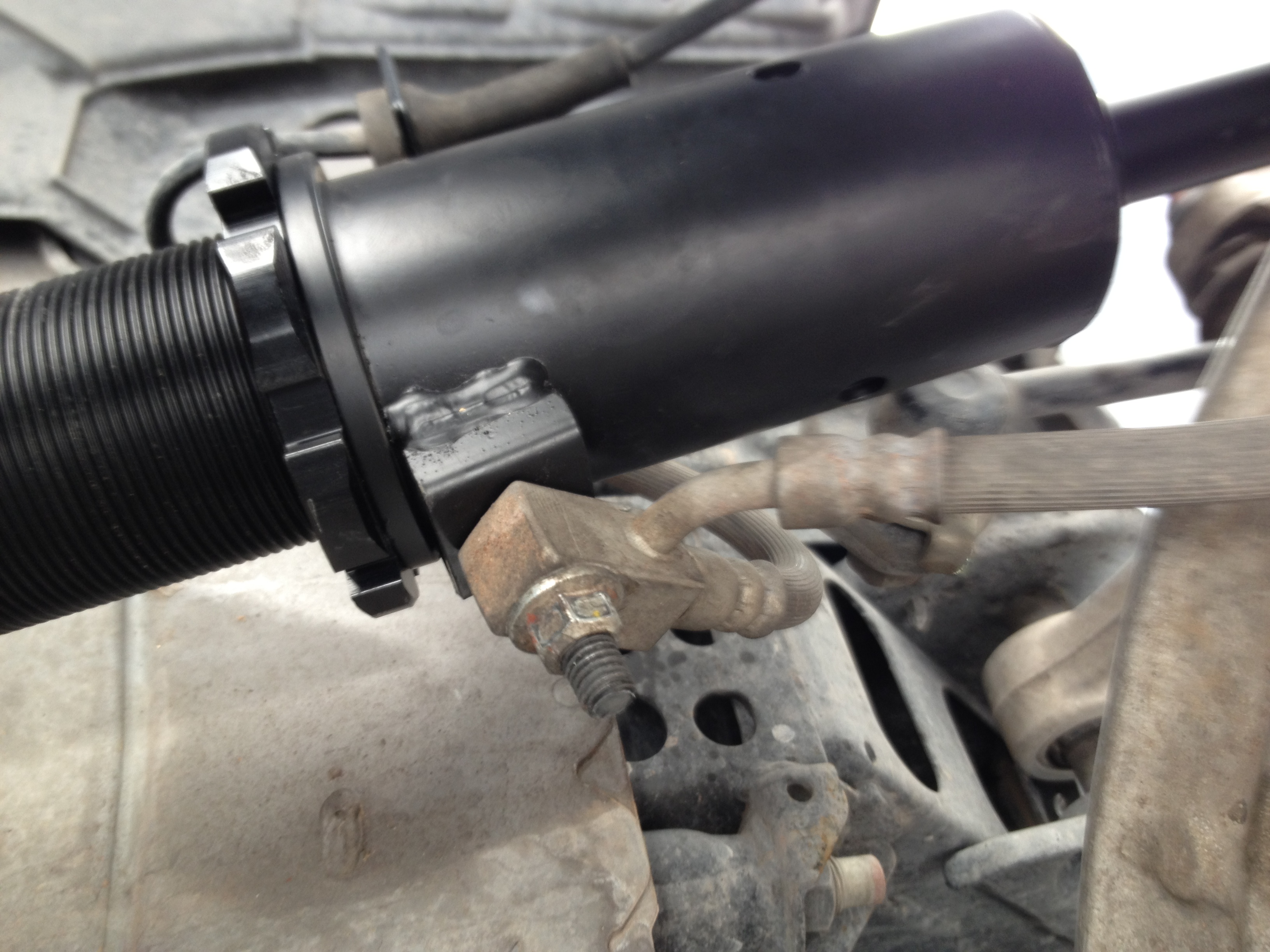
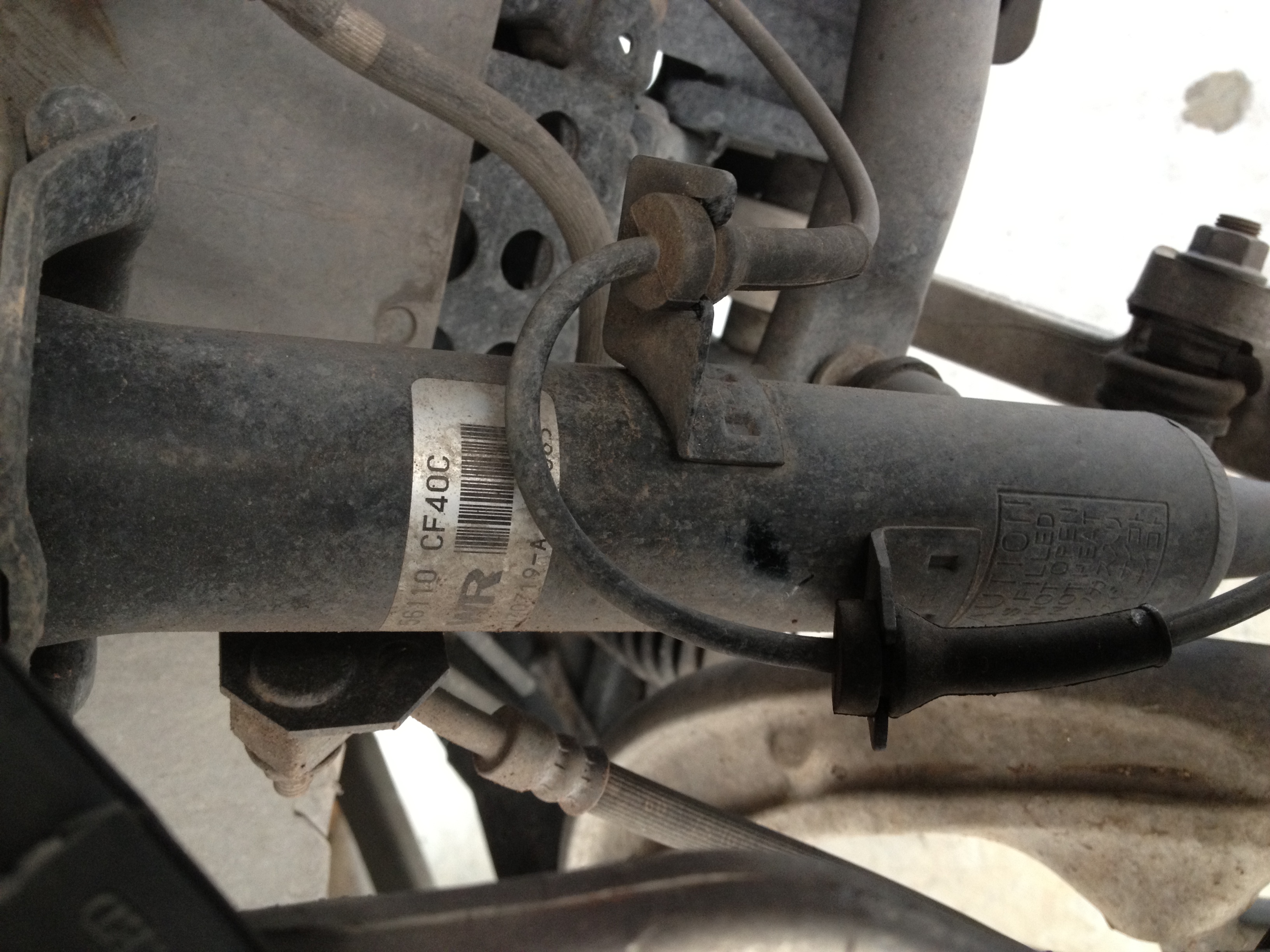
Pull the wheels off to reveal your front suspension components, and locate the brake line connected to the stud located toward the rear of the shock. Remove the 12mm nut holding the brake line to the shock, and pull the line away from shock.
Then, pull off the speed sensor wiring.
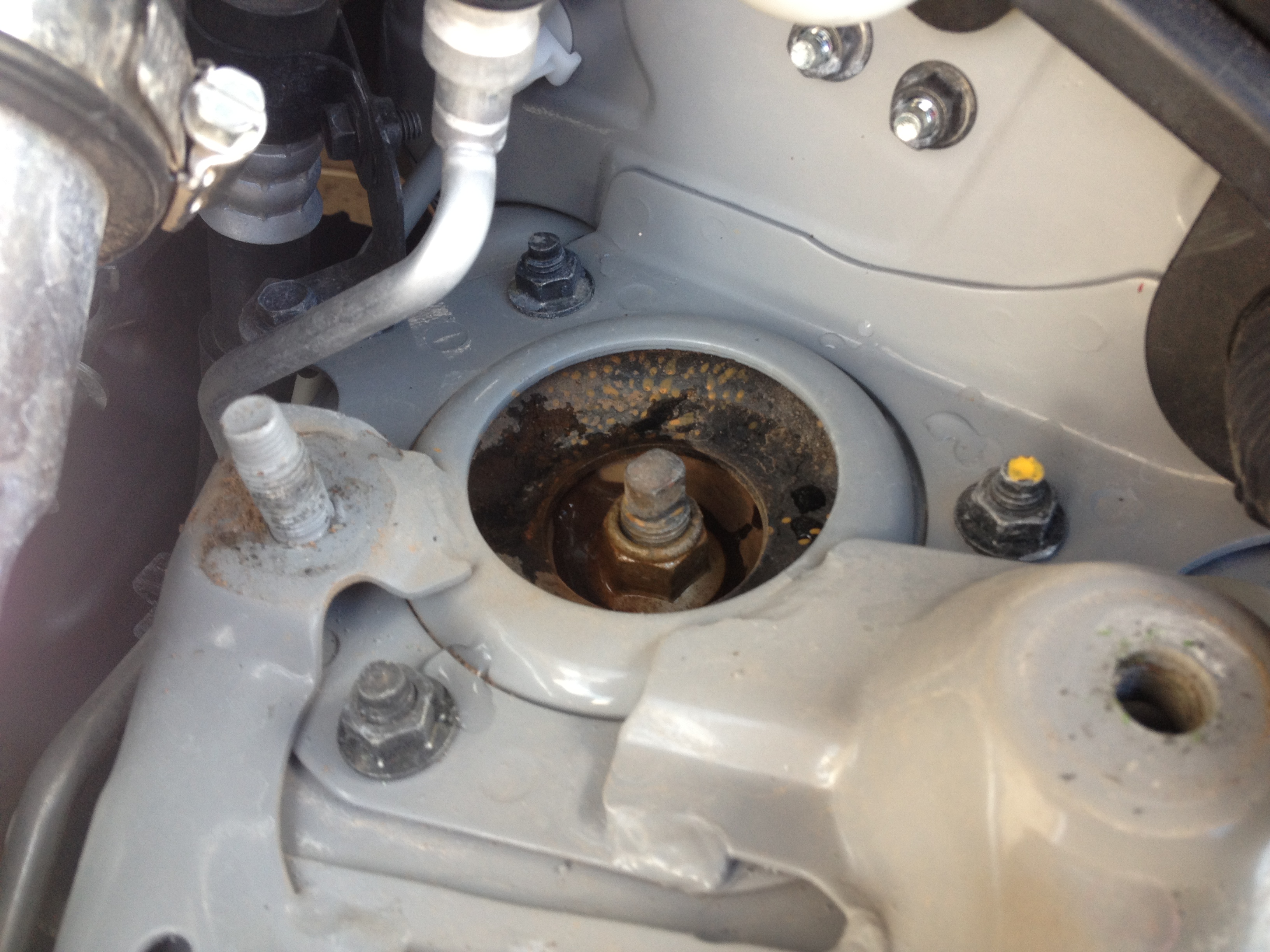
After these are disconnected, remove the strut tower bar by removing the three 14mm bolts and 14mm nut on either side. Once the strut tower bar is removed, you will see the three 12mm nuts securing the upper strut mount to the strut tower. Remove these three 12mm nuts.
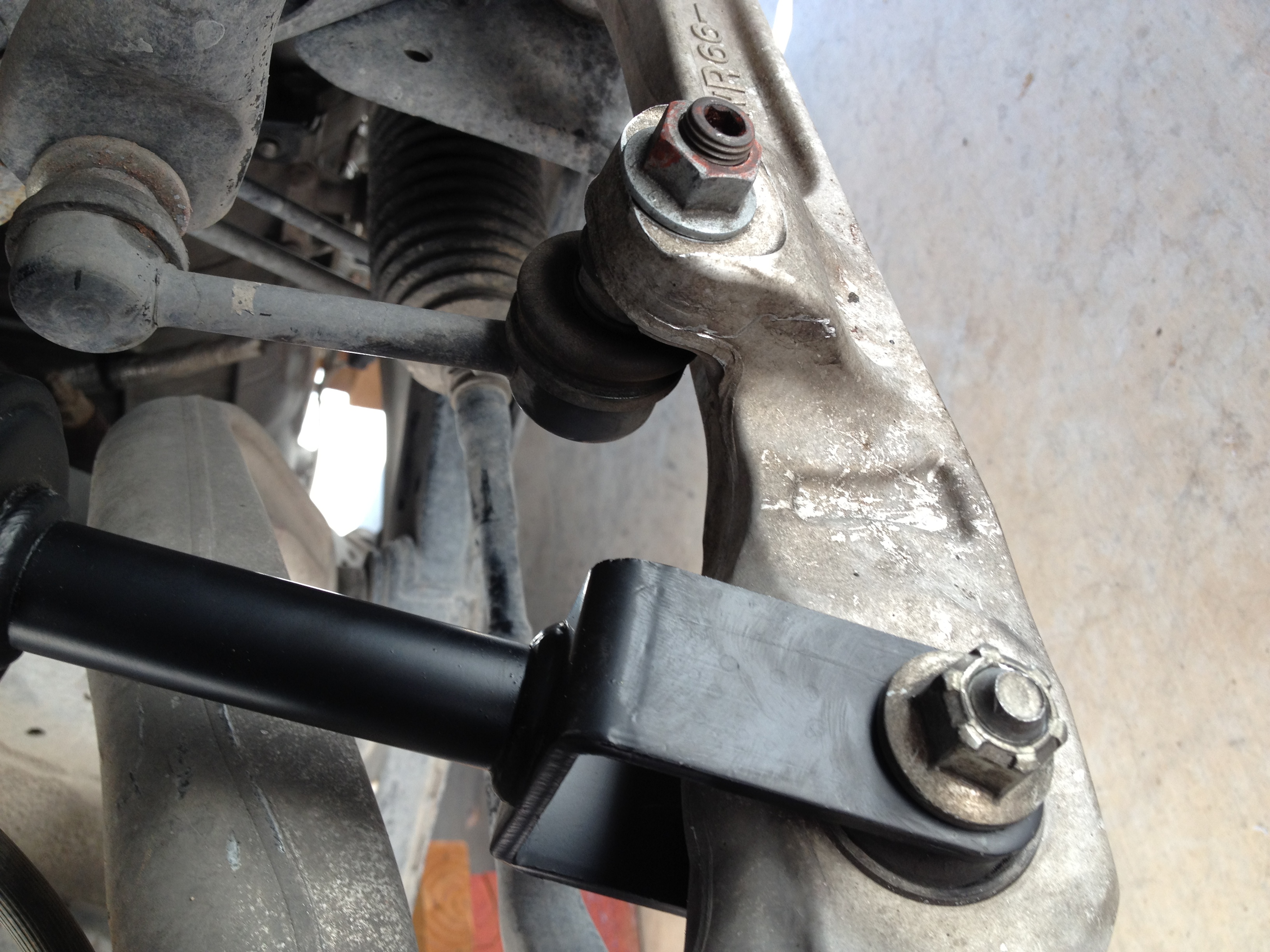
Then remove the cotter pin and nut connecting the upper A-arm to the spindle arm…
…and the 17mm nut connecting the sway bar end link.
(This allows for more downward movement of the assembly to assist removal of the stock shock)
Remove the 17mm nut/bolt connecting the strut lower mount. Now you should be able to remove the strut (top end first) by pushing down on the assembly, and up on the upper A-arm. Be sure not to pinch or damage either the brake line, or the speed sensor wire when removing the shock.
Next, determine your preferred ride height in the front. Installation is basically the exact reverse procedure of disassembly.
Into the fender well you go, with the lower mount first, looking out for the brake line and speed sensor wire. It is much easier to get the aftermarket unit in when it is adjusted for lower ride height as the entire unit length is shorter giving you more room to work with.
After installing the original 17mm bolt/nut onto the lower mount, you can now jack up on the rotor, while guiding the three upper mounting studs into place. Now re-install the upper A-arm to the spindle arm by tightening the nut, and putting the cotter pin back in place.
To secure upper mount to the strut tower, use the three included 13mm nuts, and torque to specification. Adjust preload on the spring exactly as you did on the rear, using the supplied perch wrenches. You can now re-install the swaybar endlink, as well as the speed sensor wire, and the brake line using the original 12mm nut.
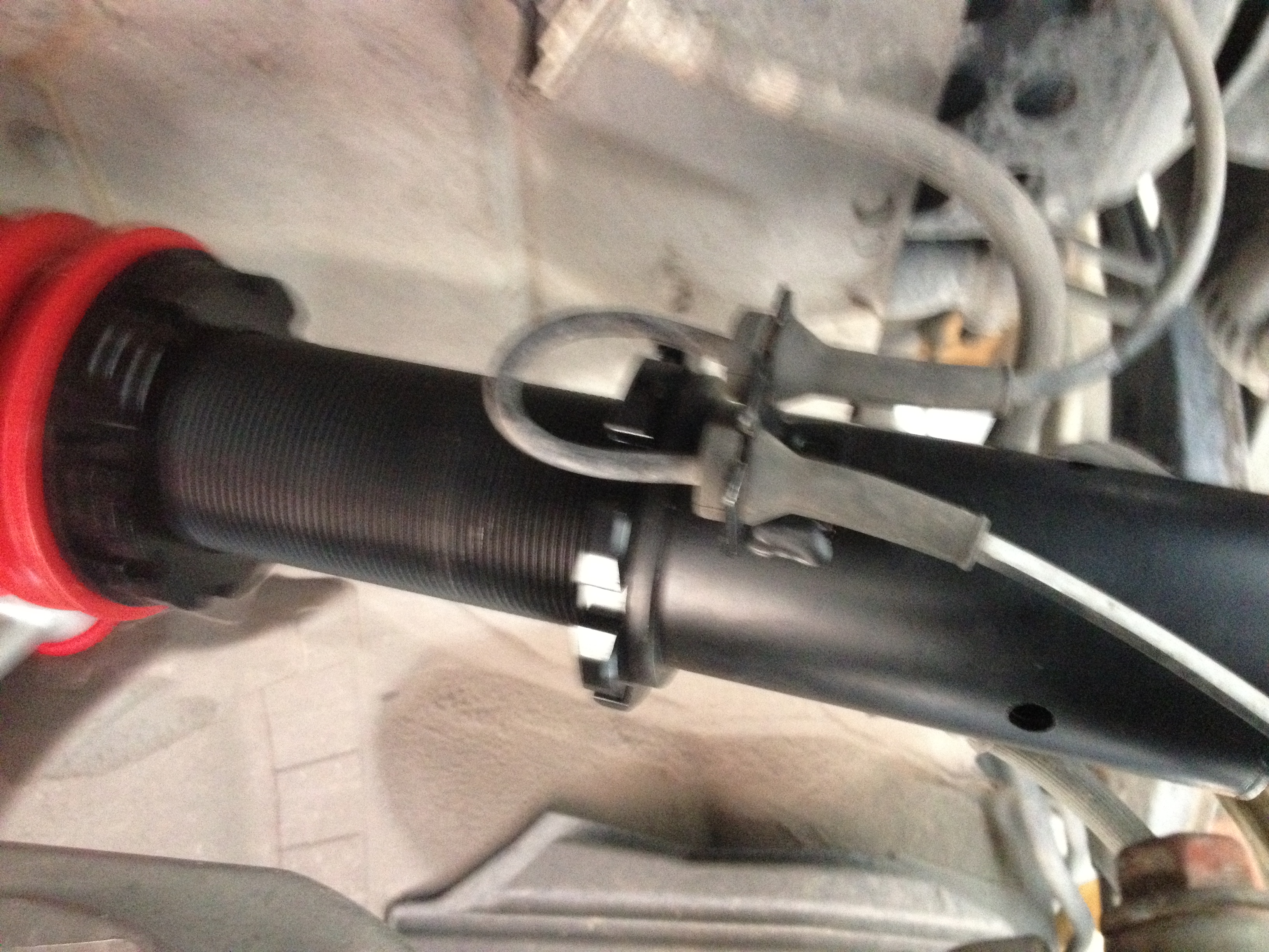
With the speed sensor wire locations on the stock strut being staggered, and the locations on the coilover being directly in-line, you can guess that there will be less slack in the line.
I waited to connect the line until the suspension was compressed. You can now put the two lines back into place, and torque all bolts/nuts to specification. Be sure to double-check every single nut and bolt dealt with.
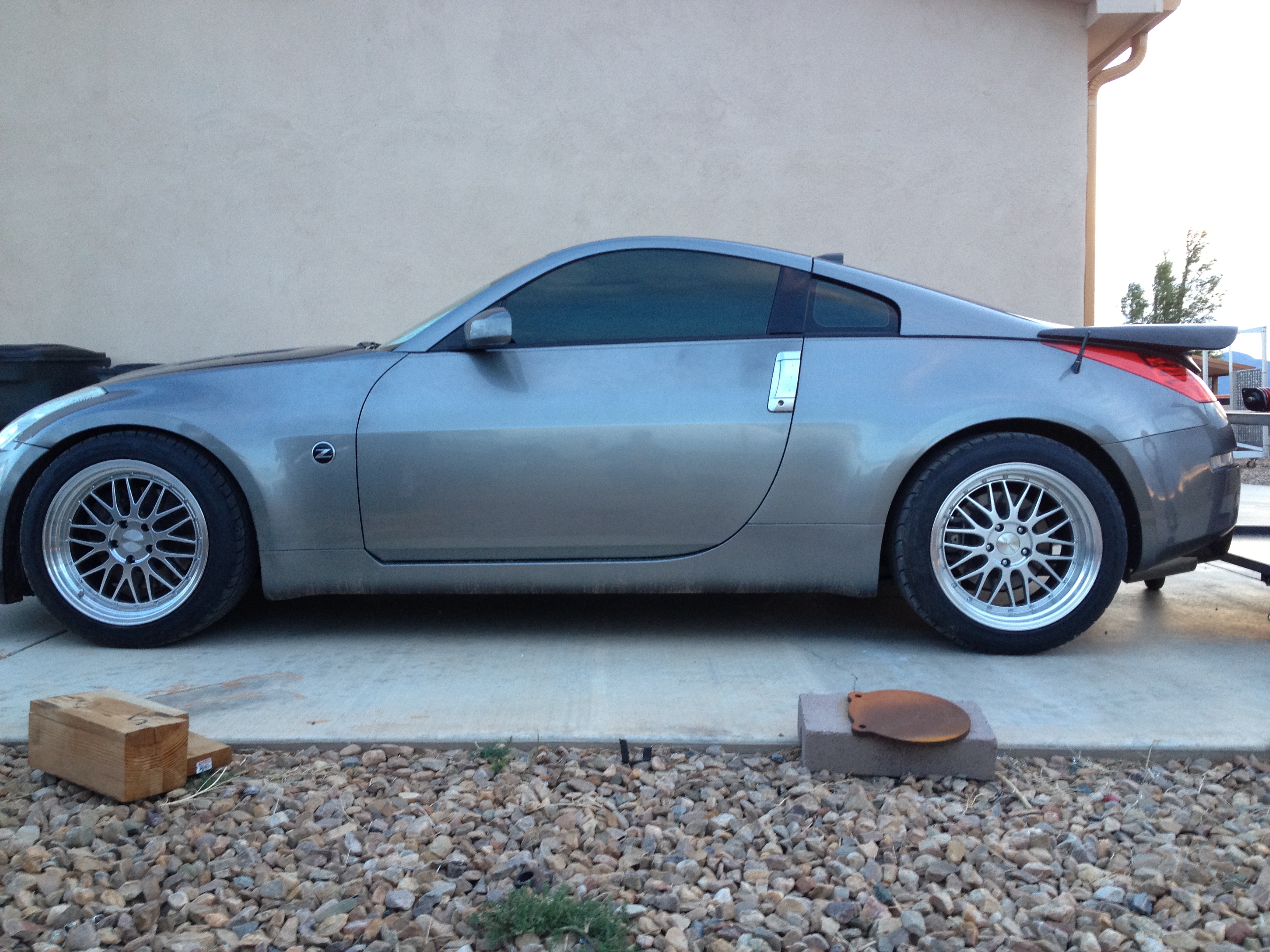
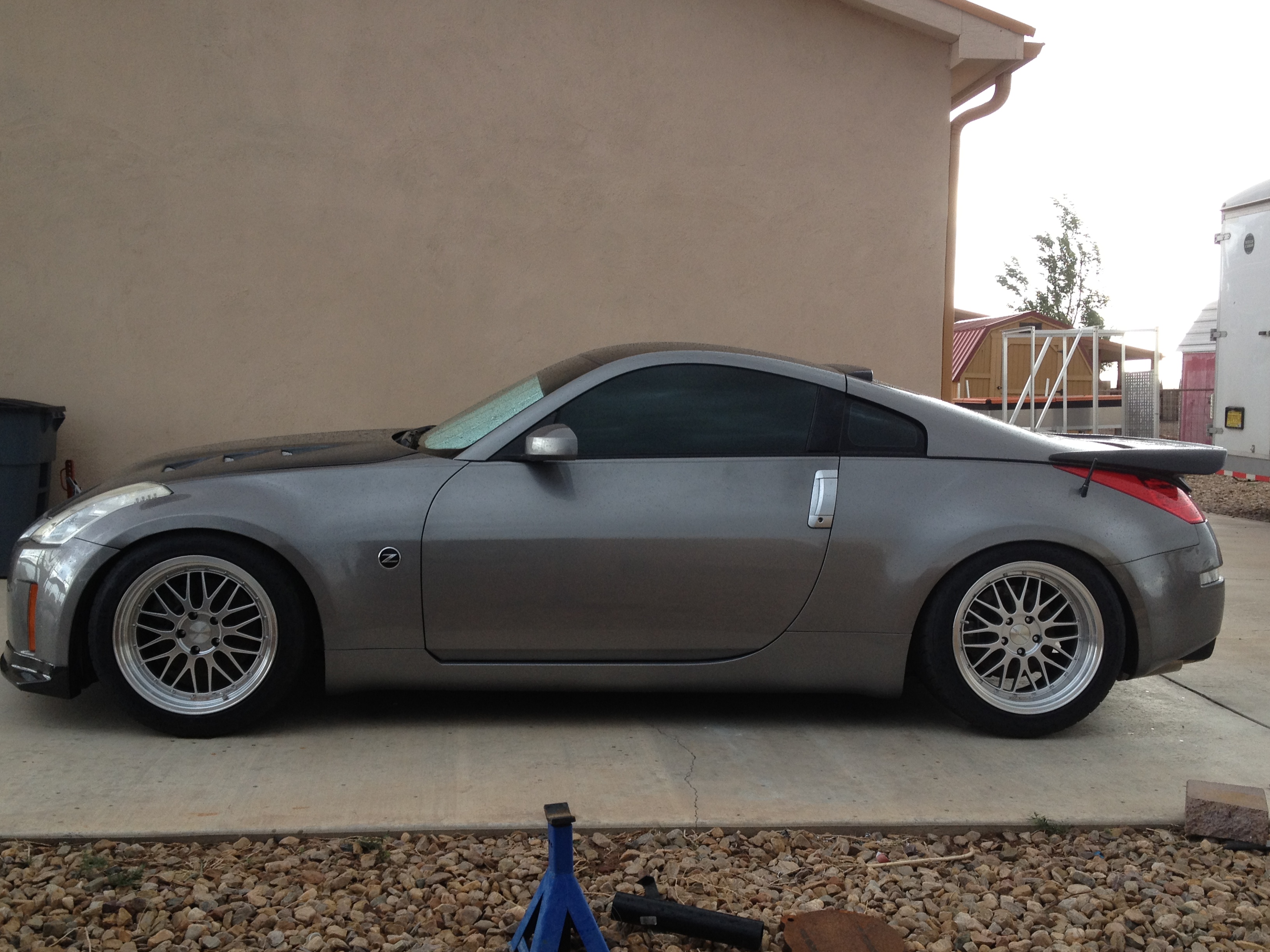
Re-install wheels, drop the vehicle back onto the ground and get a taste of your new ride height.
Before
After
This is my first time installing suspension components on the z33 chassis, so please correct me if I did anything wrong. Come on by our 350Z forum and ask any questions you may have!
Here’s a follow-up article on our impressions of the Raceland coilovers after a couple months:
Nissan 350Z Raceland Coilovers Review and Impressions
NICOclub is back again with Carlisle Events to host our 18th annual NICOFest Carlisle AutoX…
Kraft Auctions Offers Fans a Chance to Own a Piece of Datsun Racing History
We built Datsun Ranch in 2014, and it was the culmination of a lot of…
Since it's not just Datsuns that are vintage anymore ("classic Nissan" still sounds weird, right?),…
Let's talk about big brake kits for a bit. For the purposes of this article,…
What do these terms mean? Pulsed Secondary Air Injection (PAIR) Valve: The PAIR valve sends…