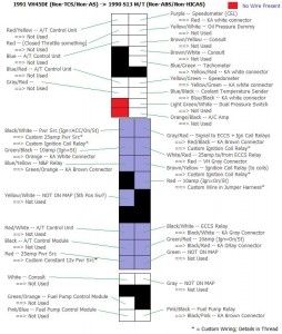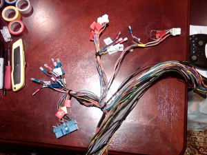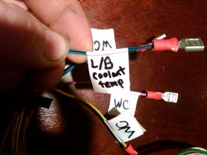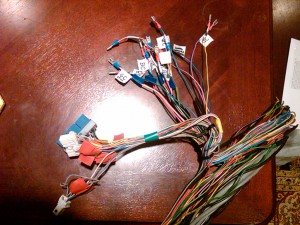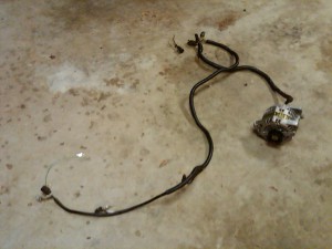
First and foremost, this is a representation of how I wired my specific application. Your application will vary and may require a slightly different materials list and install approach, unless your conditions match mine. Please read through the entire write-up and compare with your own setup before purchasing materials, cutting wires, etc. Enjoy!
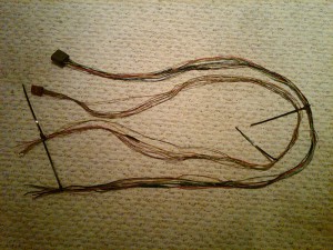
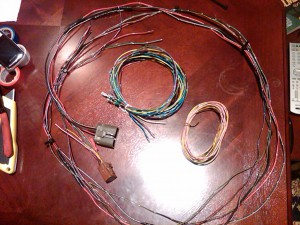
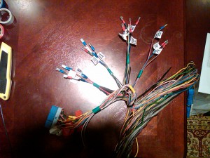
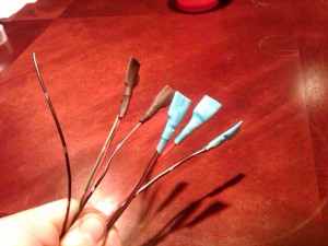
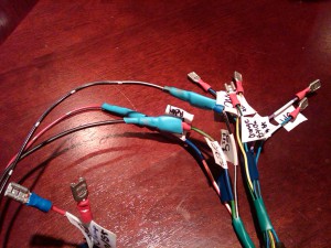
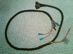
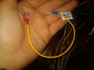
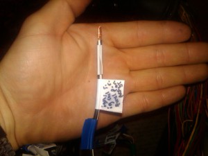
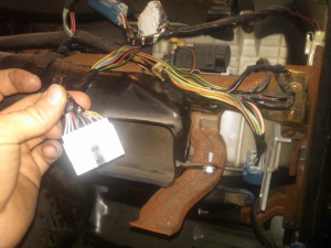
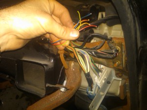
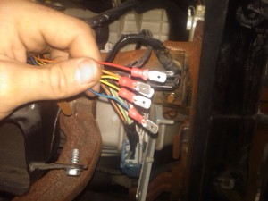
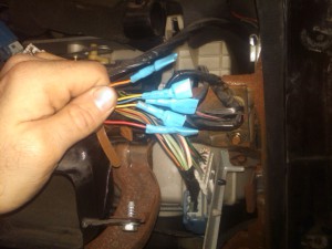
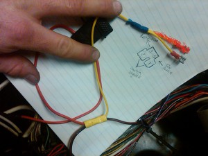
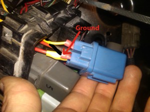
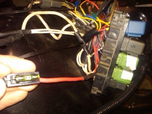
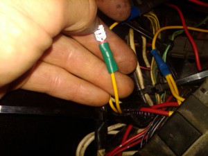
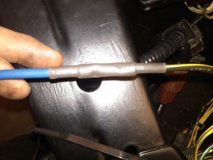
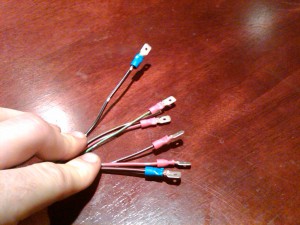
Crimp quick disconnects to the ends of each remaining wire making sure it is the opposite sex of the quick disconnects you used on the ECCS Harness. I added some heat shrink onto the end of each one and left it loose on the end so the opposite disconnect can fit right into the shroud it creates (as shown).
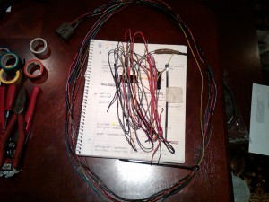
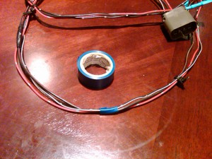
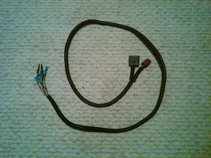
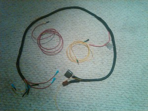
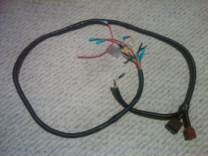
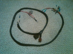
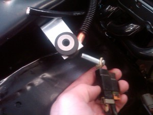
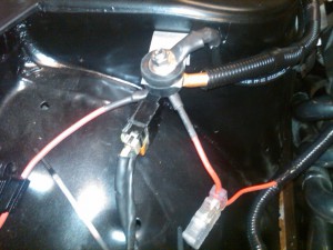
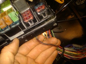
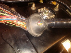
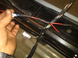
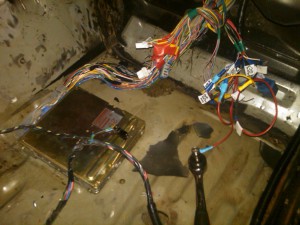
I mocked up the brown and gray harness along their path they way they would go. I zip-tied them together. This will be my jumper harness. I made a mark, using blue electrical tape, as to where my Custom Constant 12v power source with inline fuse can branch from the jumper to a 12v source. In my case, it will branch out at the location of my custom battery terminal — where I ran power from the battery in the trunk to.
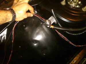
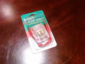
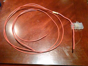
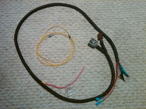
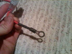
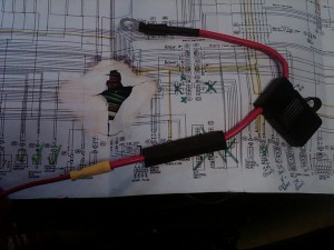
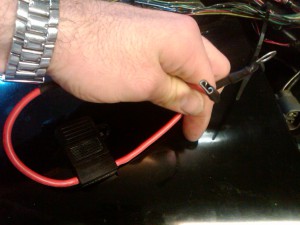
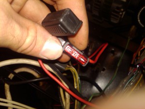
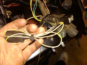
I used one of the 12ga inline fuse holders, crimped a ring terminal on the end and “butt” connected it to extend it back along the jumper through the firewall. As you notice in the picture, there are two wires coming back from the fuse holder; this is because I wanted a spare 12v constant power source inside the car in case I ever need it for something. I won’t have to cut into the jumper or run anymore wires.
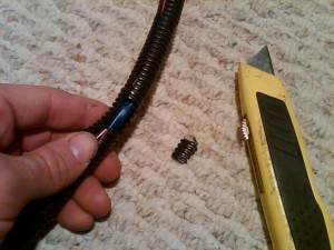
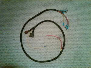
I tucked the jumper into some plastic loom. I identified where the “mark” of blue tape was and cut away a small piece of the loom to allow the wire to branch out. Then I tucked the 12v power wires into the loom as well.
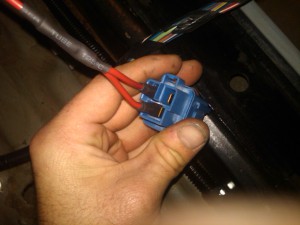
I cut a full length piece of wire for the jumper to provide for the [Red — 10amp (Ign=On/St)] wire from the blue VH connector. Tucked it in.
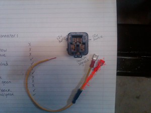
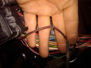
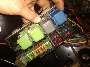
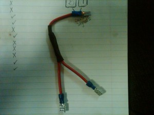
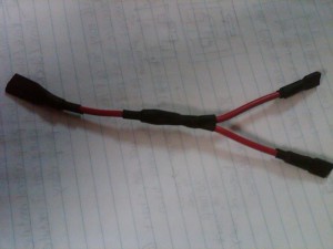
In order to accommodate an ignition coil relay (which the KA doesn’t provide) some modifications have to be made. The Gray/Red wire that sends a signal to the ECCS relay and the Ignition Coil relay still must do so. Since the Ignition Coil relay will be under the dash by the computer, we must branch from the Gray/Red wire so that it can provide to both relays. It will provide to the ECCS relay via the Red/Black wire in the jumper, and now it will provide to the Ignition coil relay via the added branch. Crimp a quick disconnect female on the branch (required).
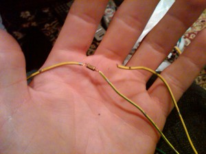
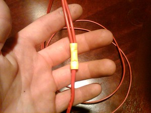
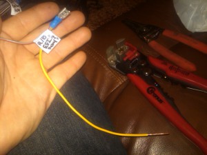
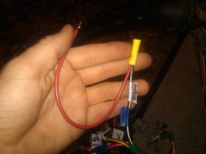
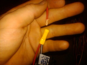
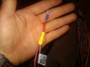
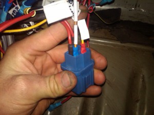
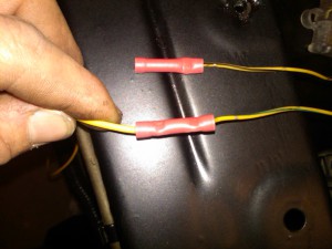
Using the same logic as above, we must branch the thicker Black/White wire from the blue connector of the VH ECCS Harness. The only difference is the direction of the signal in the wire. The Gray/Red send a signal from the ECU, the Black/White receives a power source in the ACC/ON/ST positions that goes to the ECU making a stop at the Ignition Coil relay on the way. (In my application, the power source will be at ON/ST.) Crimp a female quick disconnect on the end of the branch for this one as well (required). Since the largest female quick disconnect I had available was the blue one (not big enough for two 12-14ga wires), I used a yellow butt connector as shown below.
I have done all of this work and turned on the ACC/ON in the car, but I have not yet attempted a start. I would recommend sitting tight while I make sure it all works, haha. It should.
