How To: Wiring an RB25 into an S13 240sx
BY: opticnerv
Tools / Materials needed:
Soldering Gun/Pencil 15w-30w
Rosin Core Solder
18 Gauge Wire (buy a big roll, at least 30 feet)
Cable Tubing (To make everything nice and neat at the end)
Resources To Print
What I based this whole writeup on:
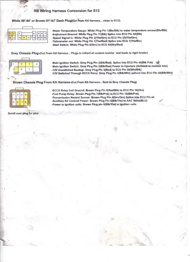
RB25 ECU Pinout
Resources to Watch
Motivation
Step 1:
Locate the brown and grey plug. These plugs will supply power to the RB25 harness. They are located near the passenger side headlight. If you removed the KA yourself, cut the male ends of the grey and brown plugs off the KA harness. Make sure to cut at least 6 inches after the plugs. If you cut the plugs off too short, soldering will be a pain in the butt. If for whatever reason you don’t have a KA harness available to use you can still follow these steps, but if you ever decide to remove the RB25 you will have to cut the wires instead of unplugging them.
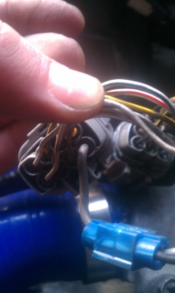
This is actually a picture of the final product but it clearly shows what the two plugs look like.

Step 2:
We to run power to the Injectors, Ignition Coils, and AAC Valve (controls idle). Before you start be aware that not all the wire colors I will mention may be the same. Use the wire colors only as a reference, and ALWAYS verify the pin location. This will save you a LOT of hassle down the line.
There’s only two wires on the AAC Valve. To be sure the blue wire is the power wire the rubber boot on the connector should be a color other than white. This goes to any other connector. The Ignition Coil Plug comes out of the spark plug cover at the rear of the engine. It’s not too far from the ACC Valve. Find the power wire on that plug. Solder a piece of wire from the ACC Valve power to the Ignition Coil power (use about 6 inches of wire). This will require you to do 3 way splice. After you’re done, find the center of the 6-inch wire you just soldered then cut and strip. You will now 3 way splice this into the Brown Plug Pin 6 (Black and Yellow).
ACC To Ignition

Cut in Half and Spliced to power

All Done

Don’t worry the rest is pretty straightforward!
From the Grey Plug Pin 2 (Black and Red) run wire to Injectors power plug (3 way splice). To find the injector power plug find the fuel rail and look for the only plug coming out of it. *Remember how to determine the power wire*.
Injector Power Wire Grey Wire.
Step 3:
Cut six (6) four-foot long pieces of wire (18 gauge).
Label each wire on one end according to what I write in bold letters and solder the other end to the corresponding plug/pin.
Wire 1: ECCS Relay Coil ECU PIN 16 (Orange) – Solder to Brown Plug Pin 8 (Red/Black)
Wire 2: Fuel Pump Relay ECU PIN 18 ( Black/Pink) – Solder to Brown Plug Pin 7 (Black/Pink)
Wire 3: Trans Neutral Safety Sensor ECU PIN 44 – Solder to Brown Plug Pin 4 (Green/Orange)
Wire 4: Main Ignition Switch ECU PIN 45 – We already soldered this to the injectors (grey plug pin 2), so three way splice the four foot section of wire with the label to the new injector wire you just installed in step two.
Wire 5: 12v Unswitched Backup ECU PIN 58( White/Black) – Solder to grey plug Pin 3 (Red)
Wire 6: 12v Switched ECU PIN 49 (Black/White) – Solder to Grey Plug Pin 5 (Black /White)
I used painter’s tape.

Slide the labeled wires into your cable tubing, then run the cables through the firewall. You will have to find the ECU pins and splice the labeled wires to the corresponding ECU pins.
Step 4:
If you got to this point, you’re close to the end. Locate the white plug under the passenger side kick panel. You unplugged this wire when you removed the KA Harness. Same thing applies from the beginning, if you don’t have the ka harness to source the male end you can solder directly.
Instrument Ground – White Plug Pin 11 (Black) Splice to ECU PIN 60 (Black)
Speed Signal In – White Plug Pin 2 (Yellow/Green) Splice to ECU PIN 53 (Yellow/Green)
Tach Out White – Plug Pin 1 (Yellow/Red) Splice to ECU PIN 7 (Yellow/Blue)
Start Switch -White Plug Pin 8 (Orange) Splice to ECU PIN 43 (Grey/Red)
Water Temp Gauge – White plug Pin 1 (Blue/Black) Splice to Water Temp Sensor (Blue/Black).
This is my second time wiring an RB25 into an S13. The first time I didn’t have spare KA harness plugs so everything was hardwired, and I used those nasty little blue clips. This time around I chose to solder everything and found some KA Plugs.
I hope this helps someone wire up their RB25 swap into their S13. If you’d like more information, or you’d like to discuss this article, here’s the place to do it! Wiring an RB25 into an S13 Discussion