
Project G35 gets blown away

After two years and 65,000 miles of trouble-free motoring in Project G35, the time had come for a much-needed increase in power. While this car sees daily-driver duty, it’s also a great platform for track action. With multiple HPDE and NASA track events under its belt, the G35 has always performed flawlessly.
Periodic bolt-on modifications increased power incrementally over the past couple years, including the addition of a JWT Popcharger intake, a Kinetix composite intake plenum, NISMO headers and catback.
Track-specific modifications include GT Spec front and rear ladder bars and strut tower brace, and Tokico D-Spec 16-way adjustable struts.
With NICOfest / GT Live at Miller Motorsports Park just a few weeks away, we wanted to get boosted and tuned right away. Last year, the G35 performed wonderfully at Miller – We kept the car on-track throughout all 3 run groups, which meant a change of drivers at the end of each 20-minute session.While the other cars got an hour of rest after each run session, Project G35 stayed on the track the entire time. Aside from some boiled power steering fluid and some shagged-out Brembo rotors and Hawk pads, the G experienced no problems despite the brutal on-track pounding it was subjected to.Very impressive, considering the intense 100-degree heat – Even more impressive was the G’s ability to hang with (and even outperform in some aspects) the STi, EVO, and Elise in its respective run groups.
A lot of research went into the selection of a forced-induction setup for Project G35. Candidates included superchargers from Stillen, Vortech and ATI. We also considered single turbo kits from Turbonetics and the Greddy twin turbo kit. In the interest of reliability and maintenance-free operation, we decided to pass on the turbocharging option. While turbo systems would allow us much more latitude for making power, our experience with Project Vert caused us to lean more towards supercharging, if only to gain additional experience in that area.
The Stillen and ATI systems were strong candidates. The ATI kit requires periodic oil changes of the supercharger lubrication, and we weren’t convinced the ATI’s fuel and timing solution were exactly what we wanted. The Stillen kit, while a robust and solid contender, requires an aftermarket hood, and their preference for warranty purposes is that it be installed at Stillen, which would mean a couple trips to SoCal – Not in our plans.
After several conversations with Frank Quintero at Vortech, we were convinced this is the system we’d choose for basic, reliable forced induction on Project G35. Frank’s knowledge of the system and his eagerness to answer even the seemingly “dumb” questions helped lock in our choice, and the deal was done. Shipping was quick, and the system arrived far sooner than expected.
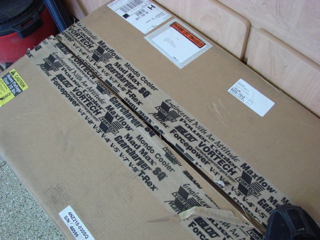
My first impression upon unpacking? This is NOT just a bunch of parts tossed in a box. Everything is packaged separately by system, and each package corresponds to a different part of the installation manual.Very handy, and very confidence-inspiring – Even the zipties are included! Since this would be a one-man installation, I allowed for plenty of time, and made sure an alternate vehicle was available for daily-driver duty, just in case I ran into a snag.
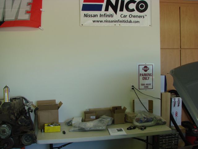
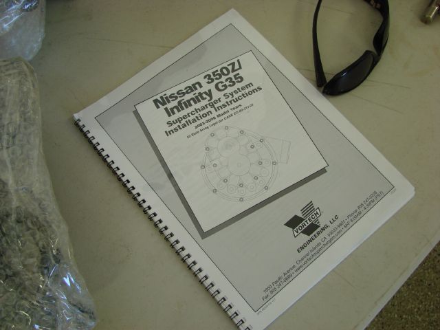
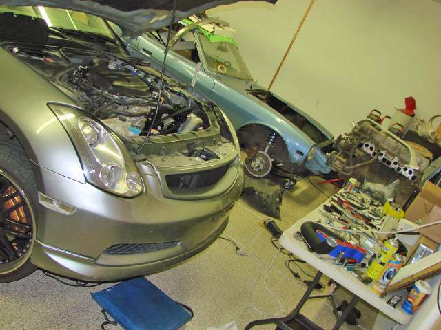
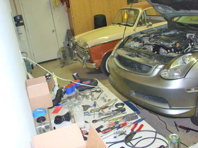
Garage space was cleared, a table for tools and parts was set up, and up on the jackstands she went. The manual is well-written and clear, and I reviewed it several times to familiarize myself with the stack of parts.
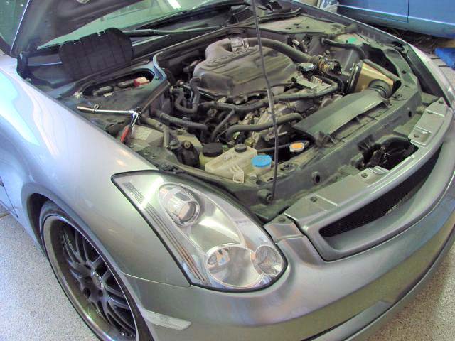
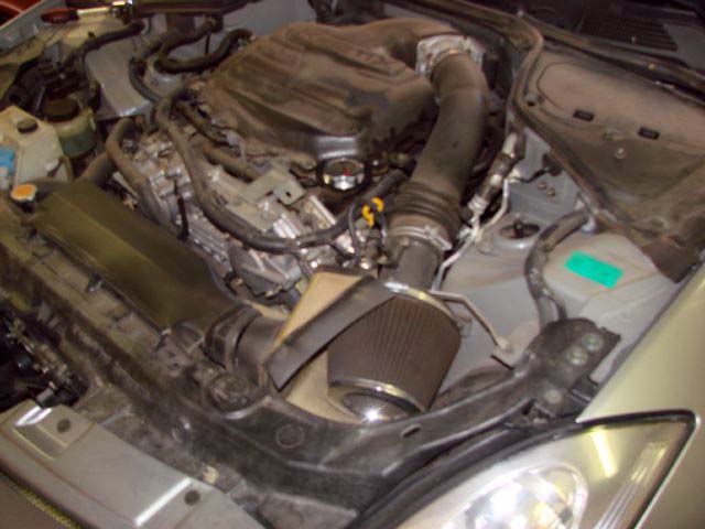
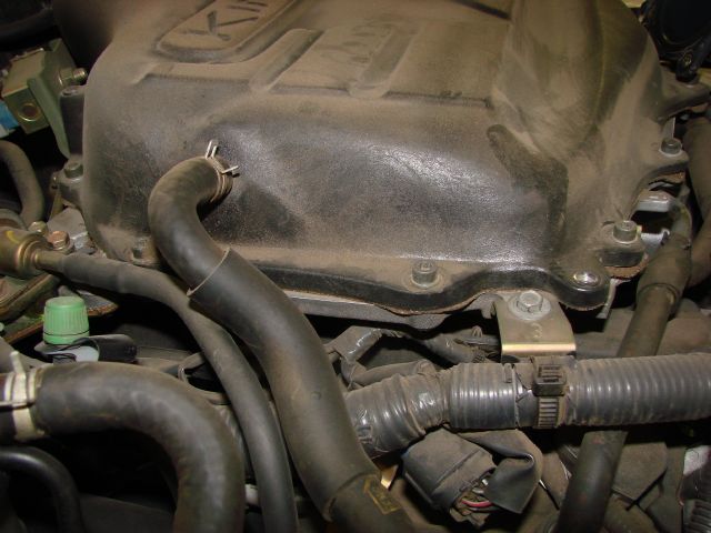
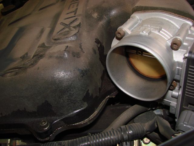
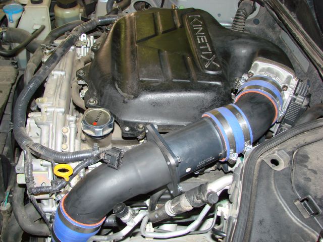
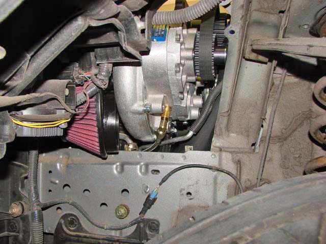
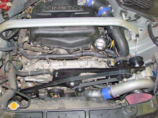
The image above is a view of the G35 prior to “surgery”. Keep in mind that this article will only cover the parts of the installation manual that, in my opinion, needed clarification, and warranted additional explanation or tips to assist you in your install. This article is certainly not exhaustive, and your experiences may be different than mine. Note the currently-installed JWT Popcharger. As you can see below, the Kinetix composite plenum was experiencing some mild leakage on the throttle body side, and the throttle body was dirty (typical of a car with this kind of miles).
Removal of the intake, the intake resonator, the air duct at the radiator support, and all associated bracketry (per the manual) was completed first.
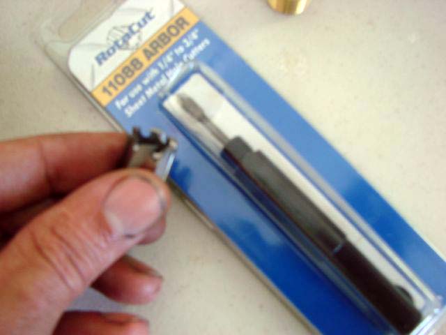
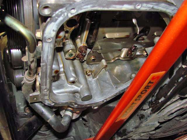
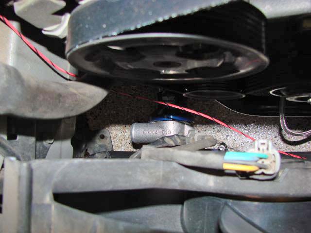
Next up, it was time to perform the installation of the oil return line. This required drilling a hole into the upper oil pan (not the lower steel pan, mind you) and threading the hole for a fitting, pictured to the left. NOTE: Although the instructions supplied with the Vortech kit allow for doing this without removal of the lower pan, DO NOT attempt it. If you’re too lazy to remove the lower pan, you don’t need a supercharger. Period.

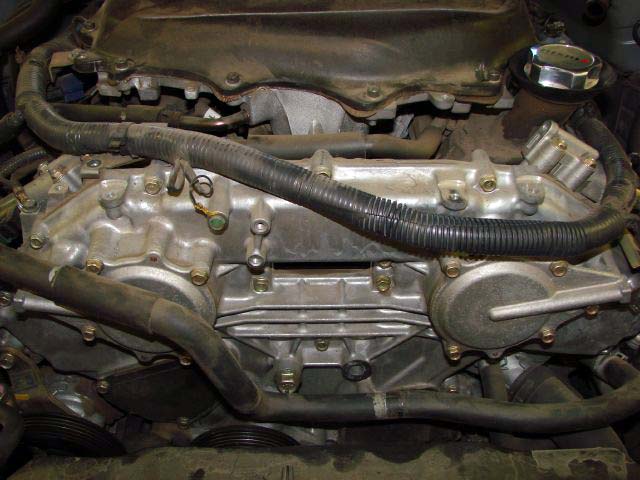
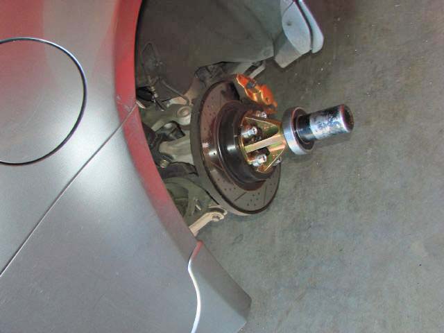
Once you’ve drained the oil and removed the lower pan, here’s the location you’ll want to drill (marked with the red/yellow target).
Fortunately, Vortech even provides the proper tool for ensuring the hole is properly cut out.
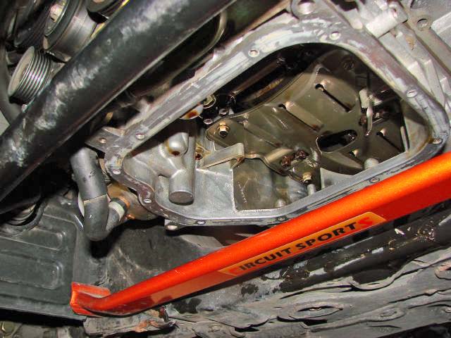
Here’s a look at the lower pan removed. I didn’t want to remove the lower suspension brace, so I unbolted the oil pickup tube from the inside and set it aside while maneuvering the oil pan out of the way.
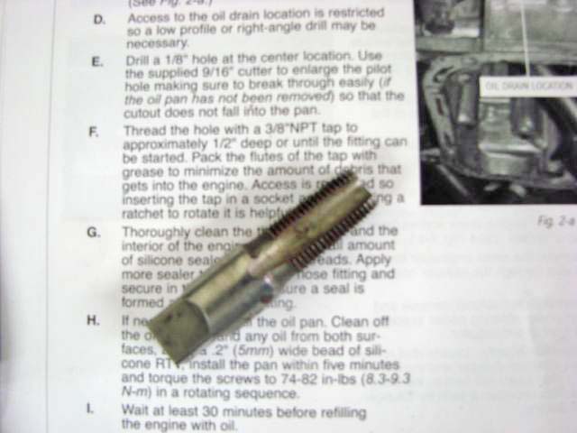
Next, you’ll need a 3/8″ NPT tap to cut the threads for the fitting. I was a little surprised that this tool wasn’t included, until I found out what one costs!
Do as I did and ask a plumber friend to borrow theirs – You’ll only use it once, but it’s a necessity. This part is a little time-consuming, as it’s hard to get any pressure on the tool to cut the threads from this angle. Be patient, use plenty of oil or other lubricant, and keep at it… You want nice, clean, precision threads here to prevent leakage!

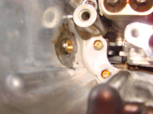
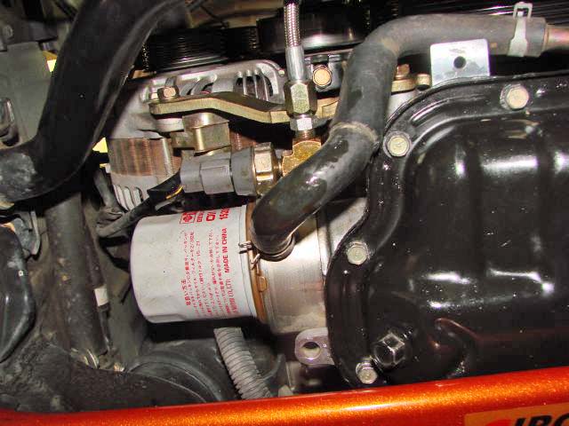
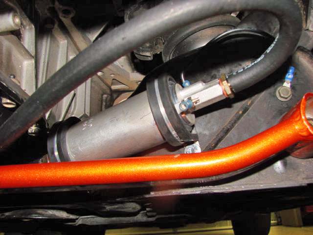
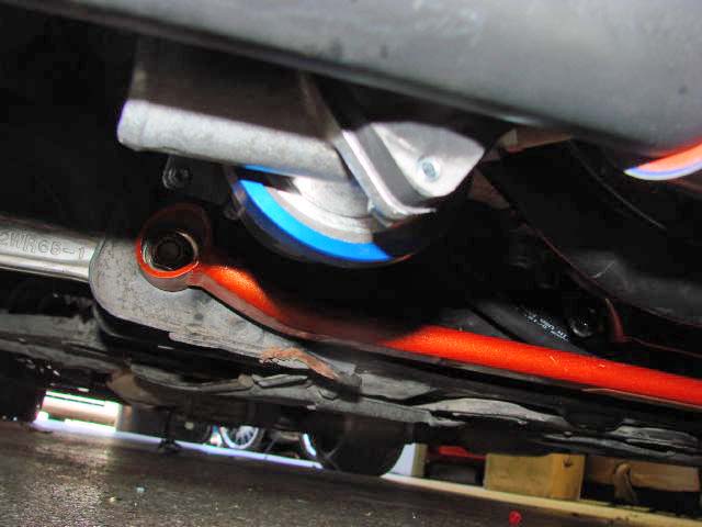
Here’s what your fitting will look like when it’s installed properly. Note the application of sealant around the threads on both sides (just in case there’s a flaw in the threads). A view from the outside (above) and a view from the inside pan (below) is included. Reseal and reinstall the pan and torque the bolts in a circular pattern, a little at a time, to the factory specs.
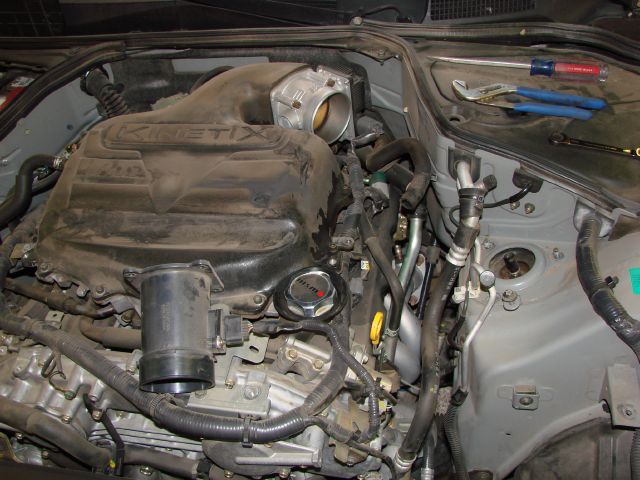
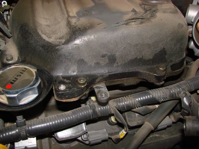
Now’s a good time to take a break from being under the car, because now you’re going up top. I removed my plenum to re-seal it. As we saw earlier, I had some seepage around the driver’s side of the plenum, and I wanted to clean up the lower plenum and throttle body while I was in there.


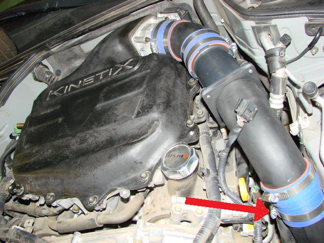
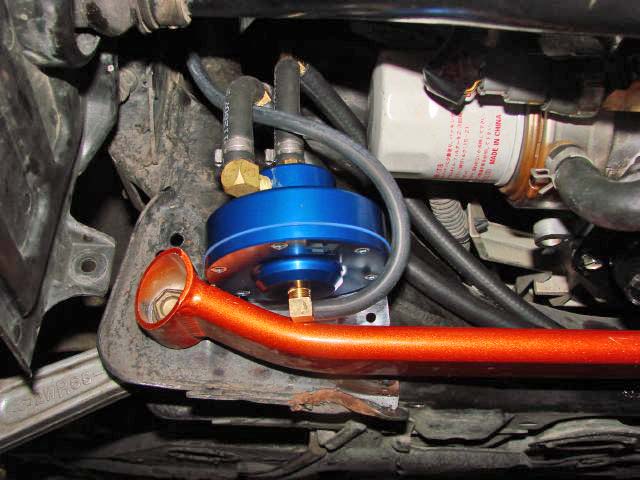
Mock up everything from the throttle body forward VERY loosely. You’ll want to adjust things as you go along, and the fitting highlighted by the red arrow is near impossible to get to once the supercharger is mounted – So make this fitting secure BEFORE doing the rest!
When are we gonna get to the supercharger????
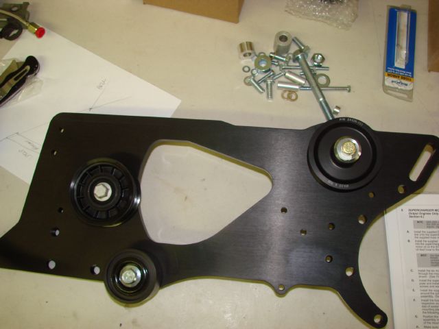

Yep – Here’s the cool part. Vortech includes all the hardware you’ll need. A metric measuring tool is handy to identify which bolt and which spacer goes where… I marked mine with a Sharpie ahead of time.
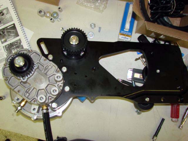
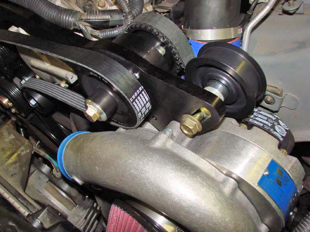
Here’s a view of the correct orientation of the supercharger on the mounting plate. The instruction manual pictures are a bit unclear, so use this as a reference.
The instruction manual recommends you assemble the oil drain and oil feed hoses BEFORE bolting up the unit. I disagree. It’s much easier to attach them AFTER the unit is securely bolted in place, then you can route them where you want them (rather than where they fall). For this, I removed the driver’s side fender well liner (the front half) which allowed unrestricted access to the backside of the supercharger. The oil feed and return lines can be easily installed from here.
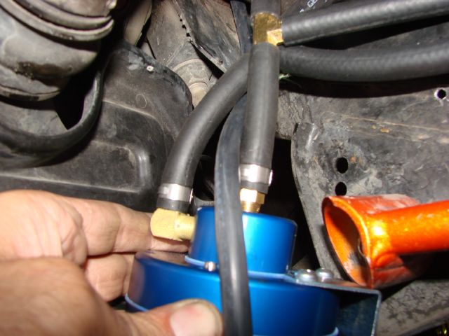
Assemble the engine side of your oil feed line as shown above.
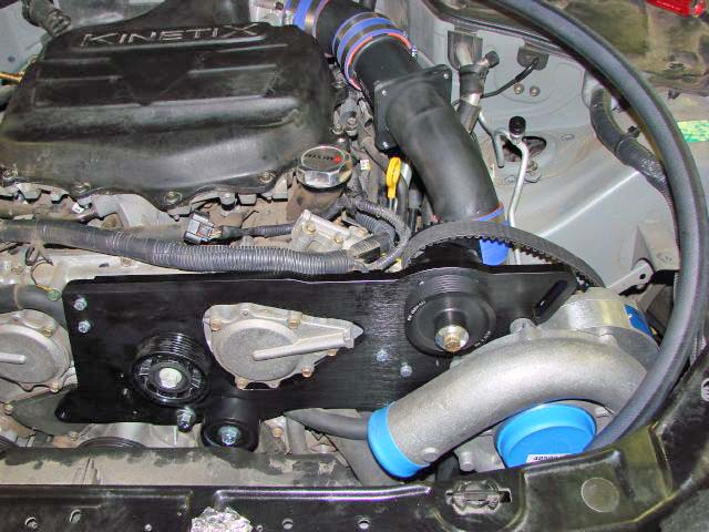
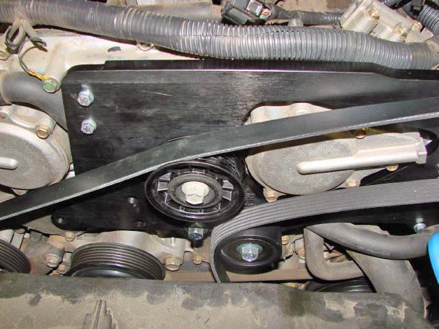
Here’s some pictures of what it looks like with the supercharger plate installed. Be patient during this part, as it’s critical to get all the spacers in the right position, get the coolant line routed in the cutout area, and make sure no wires get pinched behind the plate. As you’re installing it, you’ll be thinking, “There’s NO WAY there’s enough room for this to go back against the front of the engine”… but it does.
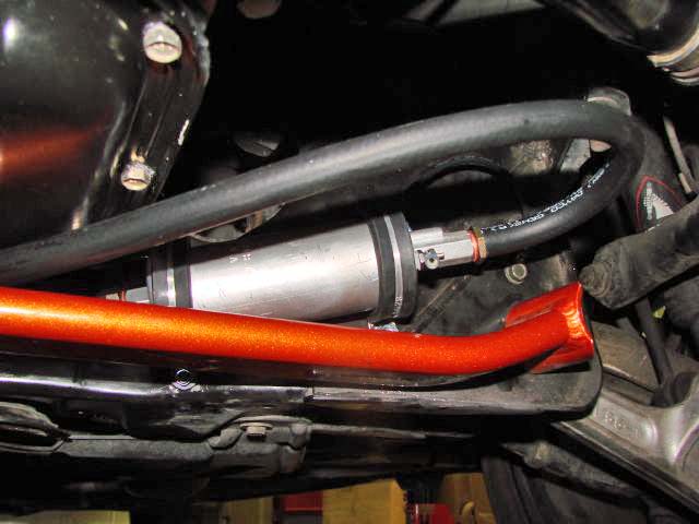
Fuel pressure controller and supplemental fuel pump are pretty straightforward – Don’t let the diagram spook you, you’re basically installing them in-line in the path of the fuel flow. The instruction manual is a little unclear on this part, so here’s a hint: Look for the green cover that protects the fuel line junction on the passenger-side frame (below the strut tower) and remove the green cover. Inside, you’ll find a bright green clip. Making sure you’re wearing protective eyewear, squeeze the tabs and pry apart the fuel line connection. Retain the clip and cover, you’ll use those to reconnect the lines to the lines coming off the supplied fuel pressure regulator.
 Vortech supplies some nifty crimp-lock fuel hose clamps, which I chose to skip in favor of some nice v-band clamps. However, if you have the appropriate tool, use the crimp-type clamps – They work well.
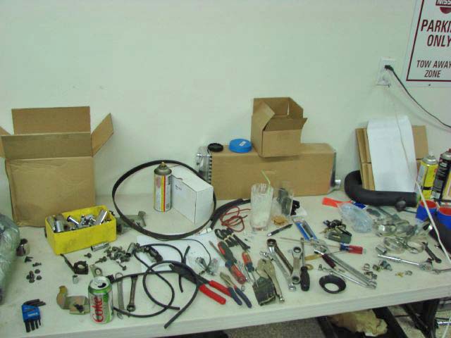
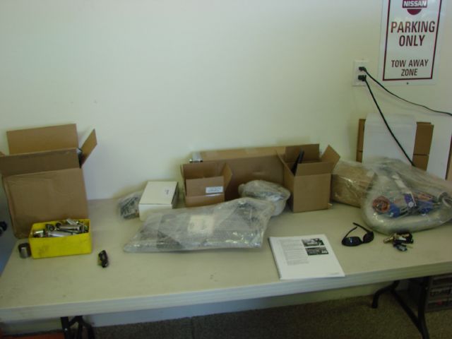
Now’s a good time to take a break, clean up your work area, and get ready for the rest of the install. Here’s my work area at NICOclub headquarters. Good lighting and a work table are a big help with any project!
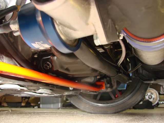
 The rest of the installation of the intercooler and piping is pretty well-covered in the instruction manual. Again, the piping that goes down in front of the motor appears to be too big to fit, but it does. Make sure it’s inserted as FAR up into the connection to the supercharger as possible, as you’ll need all the ground clearance you can get.
I believe the driver’s side pipe off the intercooler should have a little tighter bend to it, but it can be muscled into place – Your connection on that side will use ALL of the coupler to span the joint, so make sure you set aside one of the longer couplers (there are some short ones and some long ones) for this connection.
The arrangement for mounting the intercooler is so perfect, it’s scary. The bracket matches up precisely with two factory bolts (a 10mm and a 12mm) on the radiator support beautifully.
 The passenger side pipe off the intercooler is where the blowoff valve will be located, and personally, I think the placement is somewhat problematic. I’d prefer to see the valve situated on the top of the pipe, or on the outside bend, rather than on the bottom (for clearance issues), but that’s something I may address later as a custom fix. If you’re handy with welding aluminum, it might be a good idea to choose a different location for the blowoff valve. Regardless, it works fine, and if you keep all connections loose until installation is complete, you can manipulate it into place much easier.
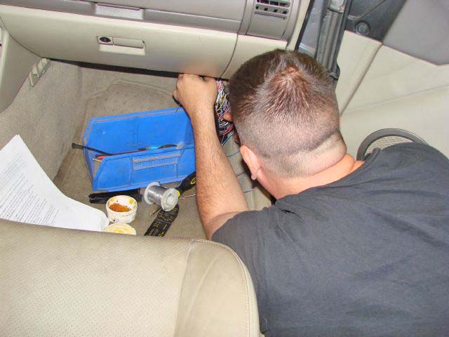
Now for the hardest part of the installation. I hate wiring, so I brought in a “pro” to assist. Jason McCoy (rotorimp), who you’ll recall from the assembly of Project Vert’s KA-T, was on hand to handle the wiring duties. Installation of the Split-Second timing control unit is pretty straightforward. Running the wiring harness into the cabin to the ECU is difficult, but not impossible. Remove the battery cover and surrounding plastic shrouding. Behind the battery, on top of the cowl, you’ll see the big rubber grommet where the main harness runs into the cabin. Punch a finger-sized hole in the rubber near the ECU harness, and here’s the trick: Get an old coat hanger and cut the ends off and straighten it out. Attach the Split-Second box wiring harness to it using electrical tape, making the transition as smooth as possible. Poke the hanger wire into the hole in the grommet and feed it down into the passenger footwell. Go inside the car and remove the kickpanel cover and the cover above the footwell, and pull the wiring through – If you attached the harness securely, you’ll fish the harness through and you can grab it and tug it into the footwell. There’s plenty of length supplied, which is handy.
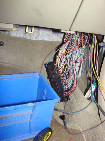
Now, you can get to the ECU plug – Pull down on the lever and it’ll pop right out. Make SURE to follow the instructions explicitly here… You’ll want to make sure you’re looking at the ECU plug from the right direction (this is CRITICAL), and use a small pick or skinny screwdriver to sort through all the wires to find the ones you need. Take your time and don’t rely solely on wire colors to ID the ECU harness wires.
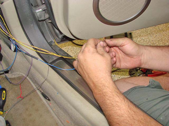
 Here you’ll see Jason performing the cut and splice. Vortech supplies some wire tap connectors, but I don’t trust these. In my opinion, a clean cut and splice is preferable. Jason’s demonstrating the proper procedure: Cut the wire, strip the ends, slide on a piece of heat shrink tubing, fan out the copper strands.Mesh them together like interlocking fingers, and twist securely, locking the wires together. Then, apply solder to the joint, slide the heat shrink over it, apply heat with a heat gun, and you’re done.
Put the rest of the car back together, tighten all connections, REFILL the crankcase with oil, and prepare to start the car. Make sure you have a full tank of premium fuel. If it starts and idles cleanly, you’ve done a good job!
Now for the fun part: TUNING!
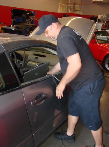
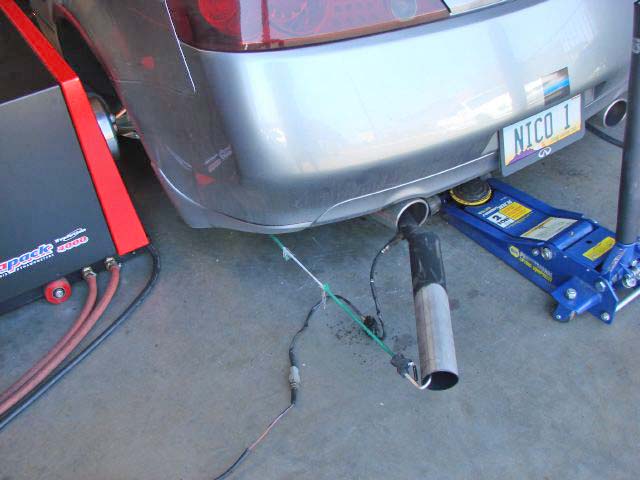
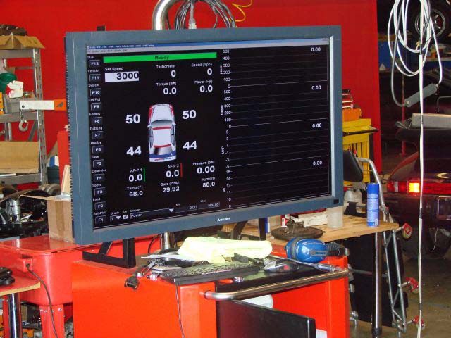
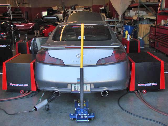
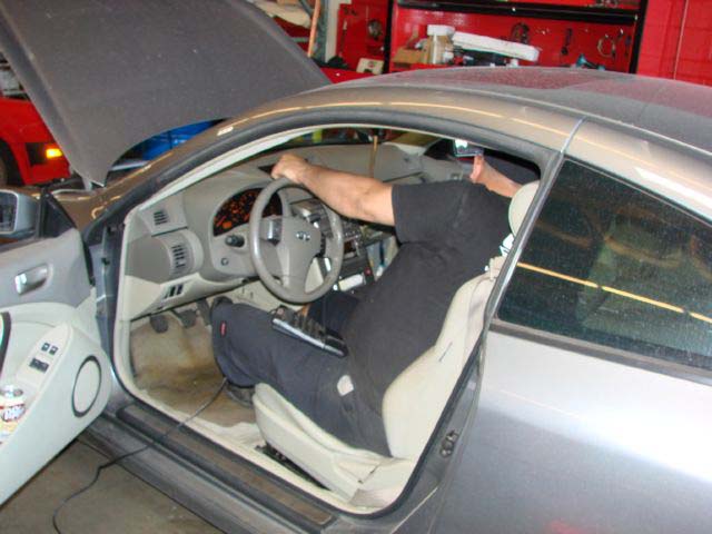
I shopped long and hard for just the right person to tune Project G35, and Tony at UMS Tuning is widely regarded as one of the best in the business. He has tons of experience tuning all types of piggyback and standalone engine management systems, and he’s tuned a ton of Nissans, so he agreed to tackle this tuning project for us. Here’s Tony prepping the G for tuning with the Dynapack chassis dynamometer:
Baseline wheel horsepower for the 2003-2004 G35 Coupe is roughly 210-220 hp, which Tony confirmed with a review of several files stored on his computer. Factory flywheel rating is 260, so that gives you an idea of drivetrain losses.We assumed a middle-ground number of 215 for our purposes.
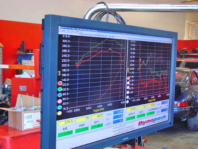
Initial pull on the dyno, prior to any tuning, resulted in 275 whp / 274 lb-ft of torque. That’s a gain of 60 whp, not too shabby.
Tony says, “That’s nothing – Let’s rock.”
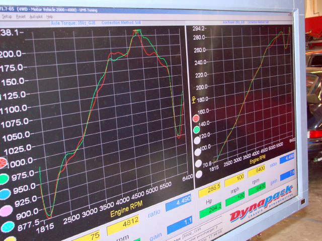

A couple tweaks later, another pull was done. 294 horsepower and 286 lb-ft of torque. Getting better! Next pull saw an improvement to 313 horsepower, good stuff!
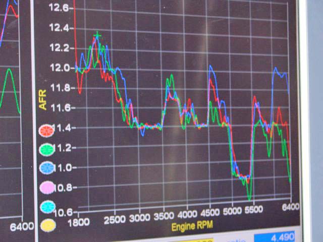
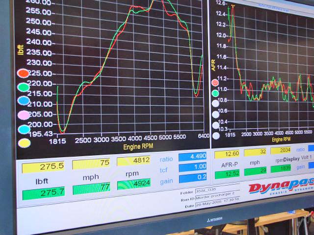
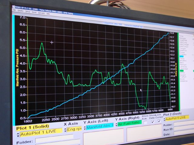 During tuning, we ran into an odd drop in AFR’s between 5000 and 5500 rpm’s. Some tweaking of the data point at 5000 rpm’s resulted in pushing the dip further up in the rpm range, but didn’t eliminate it. Tweaking the data point at 4000 rpm’s resulted in pulling the dip back down the rpm range, but again, didn’t eliminate it. You can see the corresponding small dip in power. The problem was, there’s only data points every 1000 rpms, making it near impossible to smooth out the dip. Tony addressed this by narrowing the dip as small as possible, and since it’s a dip into a richer mixture, it’s at least safe.

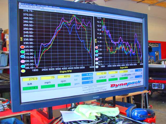
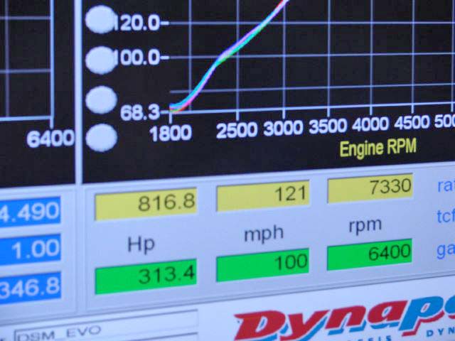
 The last and final pull, after all the fine-tuning was sorted out, resulted in 324 horsepower and 287 lb-ft of torque. This was done with some pretty conservative timing and AFR numbers, to ensure safe operation in the Phoenix heat and in case of a bad tank of fuel.
Future plans call for removing the Vortech-supplied fuel pressure regulator and supplemental fuel pump, to be replaced with a Walbro 255 in-tank pump and some 440cc injectors. We’ll be looking into a UTEC management system to allow for more precise tuning, which should net additional horsepower and eliminate a couple sources of error.
All in all, we picked up 109 wheel horsepower, a 52% increase, which is certainly nothing to sneeze at. Couple that with a relatively simple install that can be accomplished in a weekend by one guy and some basic tools, a wicked sounding blower whine, an insanely cool blowoff sound and safe, reliable power, and it’s pretty clear: Vortech has a winner on its hands.
Look for Project G35 at a track event near you!