Here’s a write-up on how to troubleshoot and repair the HVAC “Fan Amplifier” module, as used in G50 (1990-1996) and FY33 (1997-2001) versions of the Infiniti Q45, the A32 (1995-1999) version of the Nissan Maxima, and probably other models as well. This thread is the result of repairing dead fan amplifiers from IrvingQ45 and goody94q45, which they most graciously loaned me for autopsies. Total cost of the repair parts is around $4.50.
PROBLEM DESCRIPTION: When the Fan Control Amplifier module fails, either one of two things happen:
1. The HVAC blower doesn’t work on any speed setting, or
2. The blower runs at full speed all the time, and only shuts off when the ignition key is turned off.
Here’s a couple schematics that show both the G50 and Y33 versions of the Fan Control Amplifier module, what’s inside it, and how it connects to the blower and “AC Auto Amp”:
HOW IT WORKS: The Fan Control Amp receives a control voltage from Pin 35 of the AC Auto Amp; this voltage varies depending on howmuch blower motor speed is desired. The control voltage varies the conductivity of a 2SD1297 Darlington Bipolar Junction Transistor (G50 version), or a 2SK2500 MOSFET Power Transistor (Y33 version) which is connected in series with the blower motor – When the control voltage is high, this transistor conducts strongly, and full battery current is allowed to flow through the blower motor, then through the transistor, and finally to ground.
When the control voltage is low, the transistor conducts weakly, allowing only a small current to flow through the blower motor. In this manner, the blower speed is adjusted by adjusting the control voltage. The AC Auto Amp continuously measures the blower speed, via a connection between the negative side of the blower motor and Pin 34 on the AC auto Amp.
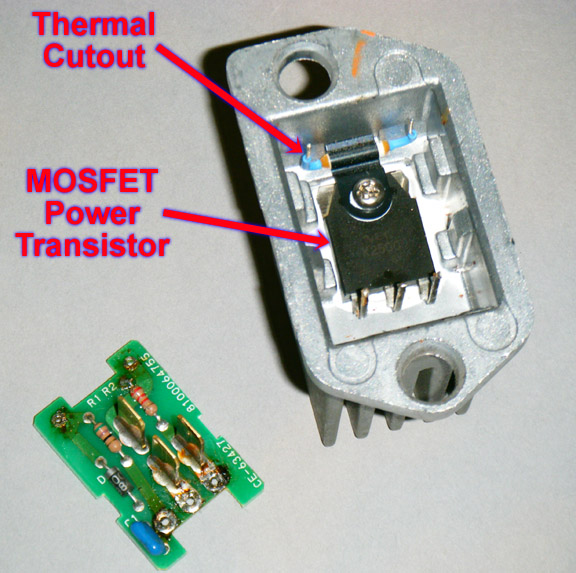
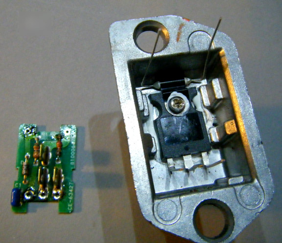
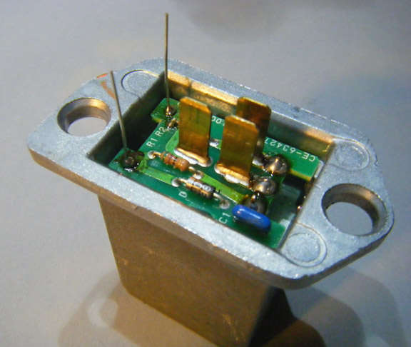
WHAT THE FAN CONTROL AMP LOOKS LIKE:
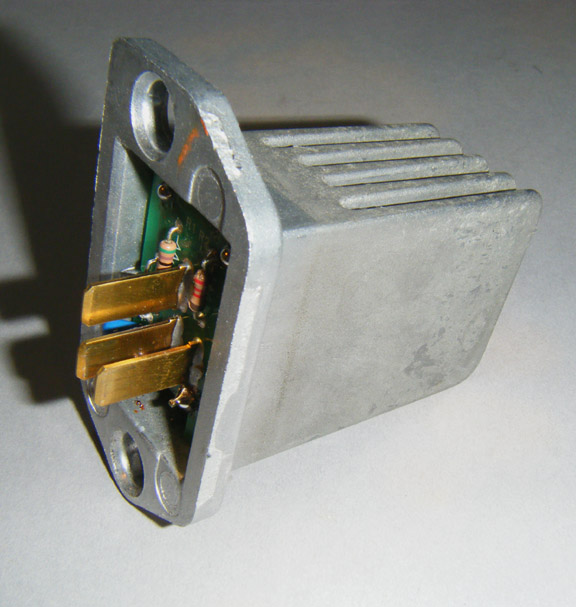
(Y33 version shown, G50 version similar)
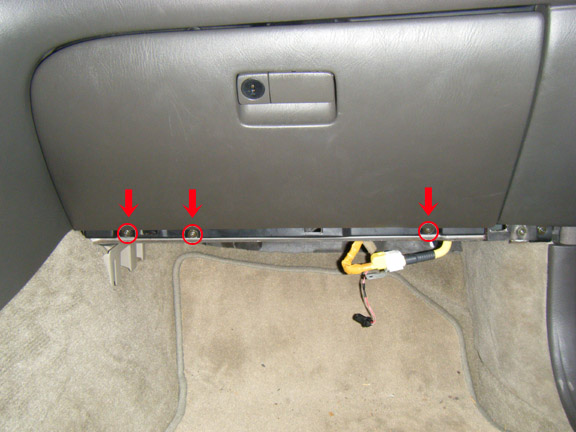
HOW TO GET TO IT FOR REMOVAL OR REPLACEMENT:
(Y33 version shown, G50 version is vaguely similar)
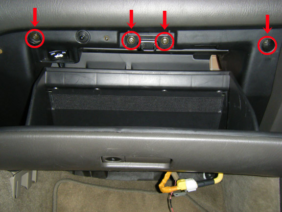
After unsnapping and pulling out the passenger side dashboard kick panel, remove these screws from the bottom of the glove box…
…and then remove these screws from the top of the glove box:
Pull the glove compartment away from the dashboard, and you’ll see where the Fan Amp is mounted behind it on the HVAC blower enclosure:
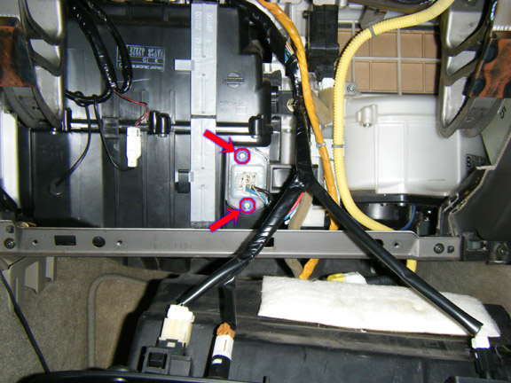
Remove the 2 screws that secure it, pull it out of the blower enclosure, and unplug it from its electrical connector.
WHY THE FAN CONTROL AMP FAILS: In looking at the schematic shown above, it becomes obvious that control voltage from the A/C Auto Amp can only reach the transistor through a thermal cutout. If the cutout blows (due to temperatures in excess of 140 degrees C.), no control voltage is applied to the base (or gate) of the transistor, and the blower never comes on.
Or, if the transistor fails, it typically develops a permanent short circuit between the Collector & Emitter (G50 version) or Drain and Source (Y33 version) terminals, causing the blower motor to run at full speed whenever the ignition switch is turned on.
HOW TO TROUBLE-SHOOT IT: If the Thermal Cutout has blown, you will measure infinite resistance between the two printed-circuit pads shown at the top of this photo:
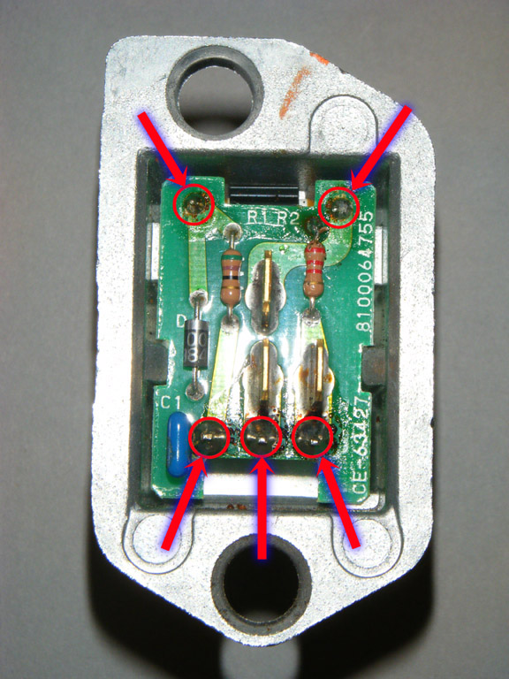
If the Cutout is still good, you will measure approximately zero ohms across these same two pads.
If the Thermal Cutout is still good, the transistor has probably blown. In some cases, this will result in the same very low resistance being measured across terminals 35 and G when probing in both directions.
HOW TO REPAIR IT:
If the Cutout has blown, a quick-and-dirty fix would be to solder a jumper wire across both printed circuit pads, thereby bypassing the cutout. However, this defeats the safety feature of having the cutout. A better option is to replace the cutout with a new one (which only costs around 45 cents).
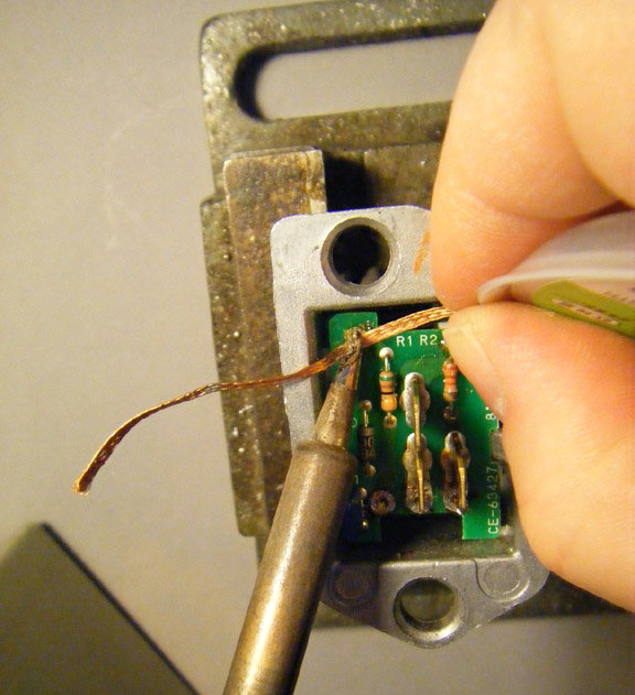
In order to replace either the Cutout or transistor, the printed circuit board must be unsoldered at the 5 points shown in the photo above. A roll of solder wick makes the unsoldering job much easier:
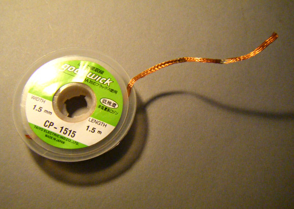
Use a soldering iron to heat both the printed circuit pad and the solder wick, until the molten solder “wicks up” into the solder wick’s copper braid. Gradually pull the braid across the pad so that fresh braid is continuously exposed to the pad and soldering iron, until all the solder is removed from the pad:
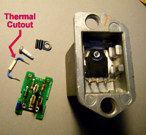
Printed circuit board removed:
Unscrew the transistor mounting screw to remove the Thermal Cutout:
On the G50, the 2SD1297 Darlington transistor (originally manufactured by NEC) is apparently no longer being manufactured, and no suitable substitute was found. This transistor has an unusually high continuous collector rating (25 amps), which doesn’t seem to be available in any currently-manufactured transistor which uses the same TO-218/TO3PF package. However, the original transistor may be available on the internet.
On the Y33, the 2SK2500 Power MOSFET is not available as a replacement part, but the Fairchild Semiconductor FDH5500 makes an excellent substitute. This MOSFET is rated to carry 75 amps, and has a very low on-resistance of 0.007 ohms. It costs around $4.00 in single-piece quantities from Mouser Electronics (Mouser Part No. 512-FDH5500).
The original Thermal Cutout is rated to open at 135 degrees C. (G50 version) or 140 degrees C (Y33 version). A replacement with a slightly higher 145 degree C. temperature is available from Mouser (Part No. 447-XYP2BN143-RC), for around 45 cents in single-piece quantities. I also bought a few extra Thermal Cutouts and FDH5500 Power MOSFET Transistors. If anyone one wants one, let me know.
Original and replacement parts, prior to bending the leads on the new parts:
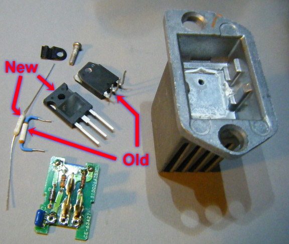
(NOTE: Apply a little bit of silicone thermal grease to the bottom of the new transistor before installing it. Permatex aluminum-based anti-seize compound can also be used in lieu of thermal grease).
New parts installed:
Printed circuit re-soldered:
Cut off the ends of the wire leads, re-install the Blower Amp in your vehicle, and you’re done.