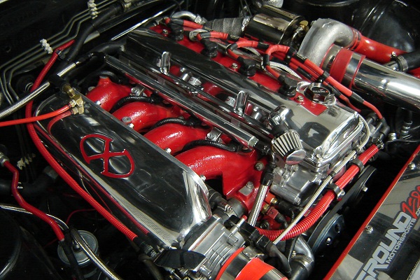
Or, “How to use compressor maps to choose a turbo for your KA-T build and predict power output.”
I made three spreadsheets for what should be the most popular turbo choices for the KA (you’ll need Excel or something that can read Excel in order to view and use them):
20G (from the Greddy turbo kit)
T04E
GT35
Basically how it works, is you punch in your variables (boost, engine displacement, volumetric efficiency, and RPM if you want), and this thing spits out your airflow at those parameters. Not only does it do that, but it plots that airflow against the compressor map.
Want to see what happens if you bore your KA out? Plug that into the displacement cell. Got another engine you want to plot? Plug in its parameters… and you’re good to go. If you’re really ambitious, you can even plot against different compressor maps.
Here’s how to change compressor maps if you so choose:
Find an image of the compressor map you’d like to plot against. Delete the current one in whatever spreadsheet you’re viewing. If the new map is in CFM, use the 20G map… if its in lb/min, use the GT35 or T04E map.
Next, you are going to have to display the axis on the plot. In office 2007, its under “Chart Tools”, and then “layout”. Display both X and Y axis. Once you have done that, paste the new compressor map in, and “send it to the back” so that the chart overlays on top of it.
Next, you just have to align the axis of your chart, and your compressor map. Right click the chart axis, and manually set the min/max/major unit to match that of the compressor map. After that, you just have to resize/move the excel chart until everything in the axis lines up… and you’re good to go!