Difficulty: 8/10 depending on install experience
Time: about 2 hours
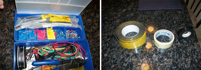
Tools needed:
– Small/medium Phillips Screwdriver
– Small/medium Flat-head Screwdriver
– Wire stripper/crimper tool
– Soldering Iron/solder
– Electrical Tape
– Adhesive foam
– Masking Tape
– Butt/Spade connectors and/or wire nuts
Parts:
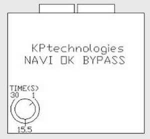
– NI35 KP Technologies NAV Bypass module ($100)
– “OK” switch core exchange board (optional)
– This will save you time and effort. ($20 extra after core return)
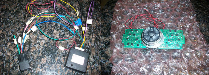
You will receive the NAV bypass module and relay not connected. Now is a good time to do all the prep work you can.
– The NAV bypass unit has an adjustment knob; turn it slightly…around the 2-second mark.
The main module has 6 wires on it:
Twisted Red – To “OK” button
Twisted Black – To “OK” button
Yellow (fused) – To Switched ignition (car purple wire)
Black – To ground (car black wire)
Green – To VSS Bypass relay (pin 85 on relay)
Purple – Reverse input (Only needed if you have a back-up camera, car orange wire)
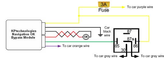
The included relay has 5 wires on it, identified by pin numbers (remove the relay from the socket to view the pin numbers)
)
Relay connections:
Pin 85 – To KP Tech VSS output (green)
Pin 86 – To Switched ignition (car purple wire)
Pin 30 – To one side of VSS wire (car gray wire)
Pin 87A – To other side of VSS wire (car gray wire)
Pin 87 – NOT USED
The connection diagram:
What I recommend is you use the masking tape to label all wires that will connect to the car wiring harness.
)
Now that the prep work is complete, lets start removing the dash parts.
– As you pull of the dash parts, label if necessary with masking tape.
1. Before we begin, put the parking brake on and move the shifter to the lowest position. You have to press the start button (with you foot off the brake) to get into ACC mode. Shut the car off by pressing the start button twice.
2. Disconnect the battery negative terminal.
)
3. Use the masking tape to protect the trim parts as shown:
)
4. Remove the shifter handle.
– pull down on the boot cover plate.
– pull the pin out with a pair of pliers. (pull towards the rear of the car)
)
5. Pull off the shifter handle straight up.
)
6. Pull the shifter plate off.
– Pull up from the rear of the shifter boot area
)
– Here is the plate off. Notice the 2 black screws…Remove them.
)
7. After removing the screws, take the AC plate off by pulling out on the bottom.
– Disconnect the wires and pull off the plate.
)
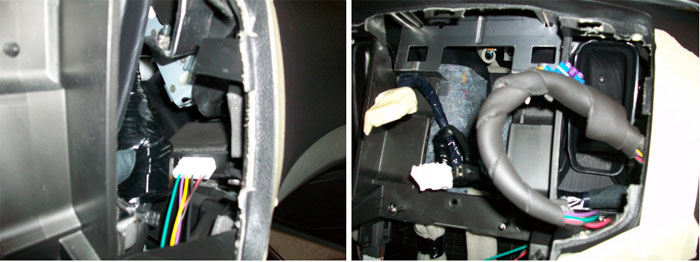
8. Remove the NAV board (with AC vents) off by carefully pulling it straight out.
– We will be removing the shown plate which houses the “OK” board.
)
– Unplug the connector and remove the cover to expose the board. A small philips screwdriver is needed.
)
– The board just comes out. Replace with the board provided by KPtech.
– If you want to solder the wires yourself (no core exchange), here’s where to do it:
)
– Route the wires through the cover plate as shown; secure it and put it aside:
)
9. Now remove 4 screws holding the Stereo head unit and the screen.
– Shown are the top 2 screws. There are 2 more on the bottom (not shown). These screws are silver…be careful not to drop them!
)
– The screen mount is beneath the stereo mount. Pull the stereo deck unit out far enough to gain access to the rear connectors.
– Pull the screen out; disconnect the wires..
– The stereo deck unit has 9 connectors that you must remove. Use a small screwdriver or your fingernails to push the tab on some to remove. It will be tight…make sure to get them all before pulling the deck!
)
10. Time to work on the connector. Here’s a great shot of it:
)
– Pull the sheath back and cut the wires as shown (The orange one if you have a back up cam…pic taken before I cut mine):
)
– Using wire strippers, pull off the wire jackets and get them ready to solder/connect.
Yellow (fused) – To Switched ignition (car purple wire)
Black – To ground (car black wire)
Purple – Reverse input (Only needed if you have a back-up camera, car orange wire)
Pin 86 – To Switched ignition (car purple wire)
Pin 30 – To one side of VSS wire (car gray wire)
Pin 87A – To other side of VSS wire (car gray wire)
– Do this by whatever methods are comfortable for you. Cut about 3 inches up so you have room to work from the connector and the sheath.
– I soldered all wires, then used butt-connectors to secure them.
– The power wire will require a larger connector because there are 2 wires going into 1. Solder the relay/NAV unit wires together. You can use a wire nut to secure the 4 wires (relay, NAV, 2 from connector) if you want.
– The black wire is also a thicker wire. Install similar to the power wire.
– The gray wire is easy as you connect each end to different wires.
Here’s a pic of the finished connector with electrical tape on all cut wires.
)
** To watch video do the following:
The light blue wire (in the picture, it’s left of the grey and white wires on the connector), is the parking brake wire. If you want to have the screen play video while moving, cut this wire and ground it permanently.
)
To make sure it’s the correct wire, use a volt meter. The wire will be negative (-) ground when the parking brake is pressed.
To actually play video, you will need to:
1. Press and hold the OK button to engage the NAV bypass module.
2. Have an ipod or other source connected to the AUX source and start your video.
**I did not do this mod as I do not want to become distracted while driving, so I can’t verify that it works.
11. Now we should have the relay and NAV unit ready to place in the car. To prevent dash rattles, use the foam tape around the NAV bypass unit.
– Disconnect the NAV bypass connector and route the wires to the upper glove box area.
– I found a nice spot shown below.
– Make sure to keep the fuse accessible.
– Wrap the wires from the NAV bypass unit with the foam tape.
– The relay went just below this area. Just make sure to keep it out of the way.
12. Continue to wrap all wires in foam to make nice bundles.
– Wrap all the way to the vehicle connector.
– Make sure to keep the red/black “OK” wires out!
– Push the wire bundles out of the way as much as possible to get it ready for the Stereo head unit. They can go on the lower right corner. Remember this is to keep dash rattles away!
)
13. Reconnect the stereo head unit. Start with the bottom connectors and work your way up.
– Mount and connect the screen.
14. Install the NAV “OK” board. Connect the red/black “OK” wires together. Make sure to cut any excess.
– I used spade type connectors so it can be removed later if needed.
)
– Wrap the wires in foam like the rest and push out of the way (towards the rear). Make sure you use electrical tape to protect the open connectors.
15. Install the remaining parts.
– The stereo head unit can now be fully installed. Look for the guide posts to align it. Remember to use the silver screws for the 4 points.
– Install the AC board. Connect the wires. The top has a few tabs that go in first, then push the bottom. Use the remaining black screws.
– Install the shifter plate. Be careful with the shifter, you don’t want to damage the leather boot area. Connect the wires. Put the front in first and push straight down on the back.
– Install the shifter handle and clip.
16. Reconnect the battery and begin testing.
– With the audio unit off, hold the setting button and turn the volume knob until it goes into test/diagnostic mode.
– Go through the menus to test the system.
To use the unit, simply hold the OK button for 2 seconds and release. When you release it, you’ll hear a click from the relay. The grayed out areas for the NAV or Audio (or any other areas) should now be accessible. When you’re done, hold OK for 2 seconds then release. Again, you’ll hear the click of the relay and you should now be able to see your position on the NAV board move.
I feel this mod is actually safer in some instances because you can still scroll through songs in the HD, which can take you’re eyes off the road longer than simply searching for what you want. In fact, BMW does not have this limit on their NAV system.
Want more articles and information like this for your G37? Pop in and introduce yourself! Infiniti G37 Owners’ Forum