…another remarkably helpful article from VStar650L!
So you want to add fog lights to your Nissan, but you don’t want to spring for a brand new Combination Switch to use the factory control on the headlight stalk. Or maybe you bought an Auto Headlight sensor and want to wire your regular headlights to work on Auto like the SL model. Or maybe you’re adding a rear wiper to something that didn’t come with one.
The factory IPDM has outputs to work with all of those, but only if the BCM tells it to work. That means accessing the dreaded Combination Switch, so maybe you just swallow hard and route wires for the relay that came with the kit. Or maybe you just decide to skip it.
Don’t. Combination Switches are only mysterious because they’re “active matrix” types, but the truth is, fooling the BCM only takes finding the right wires in the ESM, then adding one diode to your switch. That’s it, no rocket science needed. What you do need is the documentation, plus a simple understanding of how these switches work.
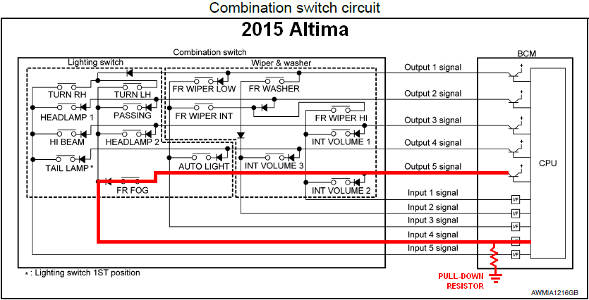
So let’s start with understanding them. Here are two diagrams, the first is the N-channel system used on most older Nissans, the second is the P-channel type used on most newer ones. I’ll get to the difference in a second.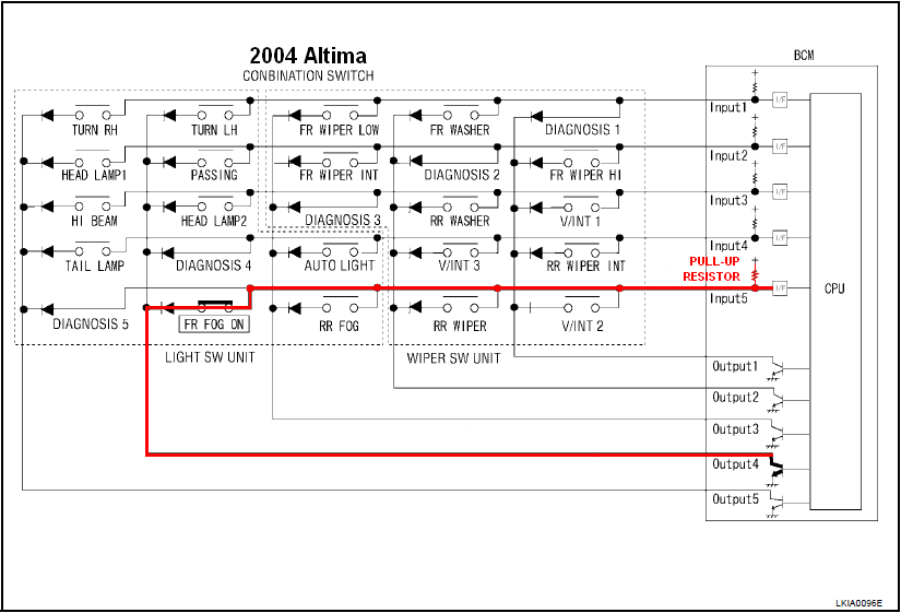
In both diagrams, the red line shows the path electricity takes when the Fog Lamp switch is activated. You’ll notice all the switches in both matrices have diodes on them. Think of a diode as a 1-way valve for electricity, current can only flow from the arrow end to the barred end and can’t flow the other way. On a real diode, the barred end or “cathode” is marked with a stripe so you can get the polarity right when installing it. For our purposes, any common diode will work, 1N4001/2/3/4, 1N914, 1N4148 are all good types and all easy to find on eBay or Amazon. What the diodes do is prevent cross-talk between the switches. In other words, if you install a switch across the matrix without a diode, then the output will cause all the switches in that row to read “on” when the BCM checks them. So on the ’04 diagram, every time you turned on the Front Fogs, the Rear Fogs, Rear Wiper, and Intermittent Wiper 2 would all turn on with it.
Here’s why. The way these switches work is that the BCM polls or “strobes” each of the output wires once every 10 milliseconds. The ’04 uses an N-channel transistor, which means it grounds the wire when polling. The input wires all have a “pullup” resistor, which provides voltage to the input line, but the pullup can be overpowered by the output transistor if the switch is closed to connect the two. So you can see that when the Fog switch is off and the BCM polls output 4, input 5 will remain at voltage because of the pullup, but if the Fog is on, the transistor overpowers the pullup and input 5 becomes grounded. The BCM simply turns on each output one after another and then reads all 5 of the inputs. Each input that reads 0V is on, each one that reads 12V is off.
The only difference with the ’15 is that it works in reverse, the transistors are P-channel types that provide voltage and they drive inputs with pull-down resistors that provide ground. The principle is the same, but a “high” input means on and a “low” means off, opposite from the ’04.
This means to add a switch, all you need to do is identify the correct input and output wires and add a diode to your switch that points in the same direction as the one in your diagram. The BCM will then think your switch signal is coming through the Combo Switch. The diagrams and switch documentation can all be found in the BCS section of the ESM. We’ll use the ’15 Altima as our example and add a Fog switch. We know from the BCS diagram that the Fogs are Output 5 by Input 4. We then go to the EXL section and find the Fog diagram, which shows us this for the BCM and Combo Switch connections: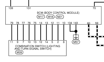
The combo Switch connector callout won’t have signal names on it, but the BCM will. So two pages down, we find the connector diagrams for M17 and M18 on the BCM: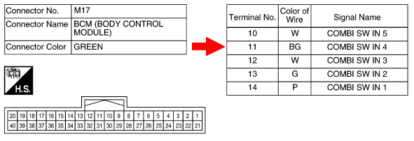
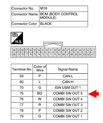
Going back to the wiring diagram, this tells us Out 5 and In 4 connect to pins 13 and 2 on the Combo Switch connector, and both wires are beige: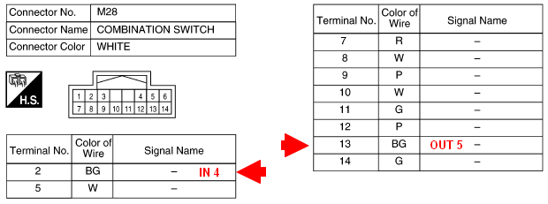
Now we have all the info we need to mess with the BCM’s little brain. Using T-taps or scotchlocks, we simply pull the steering column trim and connect our switch and diode like this (NOTE: It doesn’t actually matter which side of your switch the diode is on, only that the cathode on the diode faces in the same direction as the diodes in the Combo Switch):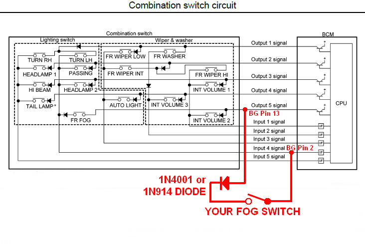
And voila, we can now throw our switch and the IPDM will turn on the factory fog prewires just like the factory setup.
Hope this helps you, and happy motoring!