Checking the TPS and Adjusting the Idle
The TPS is there to tell the ECU how hard you have your foot on the gas. It isn’t there to adjust for the idle. It’s a sensor. It does have some adjustment of it’s own and we’ll try to give our version of what our Factory Manual says (though we won’t even come close to doing it justice):
Throttle Sensor & Soft/Hard Idle Switch
The Throttle Sensor responds to the accelerator pedal movement. This sensor is a kind of potentiometer which transforms the Throttle Valve position into output voltage, and emits the voltage signal to the ECU. In addition, the sensor detects the opening and closing speed of the Throttle Valve and feeds the voltage signal to the ECU.
Idle position of the Throttle Valve is determined by the ECU receiving the signal from the Throttle Sensor. This system is called “Soft Idle Switch” and controls engine operation such as fuel cut. On the other hand, “Hard Idle Switch”, which is built into the Throttle Sensor unit on the A/T equipped models, is not used for engine control.
Trouble Diagnoses:
1. Disconnect Throttle Sensor harness connector.
2. Make sure that resistance between terminal #1 and #2 changes when opening the Throttle Valve manually.
Looking at the “pins” of the connector w/ the locking tab of the connector pointing up, terminals #1 is the one on the LEFT. #2 is in the MIDDLE and #3 is on the RIGHT.
The results of the test should be:
Accelerator Pedal Condition Resistance in k Ohms
Completely released Approx. 2
Partially released 2 -10
Completely depressed Approx. 10
If test shows “No Good”, replace Throttle Sensor.
Adjustment:
If Throttle Sensor is replaced or removed, it is necessary to install in proper position, by following the procedures shown below:
1. Install Throttle Sensor body in the Throttle Chamber. Do not tighten bolts. Leave bolts loose.
2. Connect Throttle Sensor harness connector.
3. Start engine and warm up sufficiently.
4. Measure output voltage of Throttle Sensor using voltmeter.
5. Adjust by rotating Throttle Sensor body so that the output voltage is 0.45 – 0.55 volts.
6. Tighten mounting bolts.
7. Disconnect Throttle Sensor harness for a few seconds and then reconnect it.
With the locking tab of the connector pointing up and looking at the back of the connector as the wires from the wire harness go into it, terminal #1 is the one on the LEFT. #2 is in the MIDDLE and #3 is on the RIGHT.
Output voltage is measured across terminals #2 and #3 from the harness side of the connector.
POWER SUPPLY:
Disconnect the TPS harness and look at the terminal side of the connector. (this is the side with the terminal connectors in it) With the locking tab pointing UP, the terminals are A, B, and C, from left to right.This is measured from the male half of the connection that goes to the engine.
Turn the ignition ON and measure the voltage between terminal C and ground. It should be approx. 5v.
GROUND CIRCUIT:
Ignition OFF. Check for continuity between terminal A and ground. Continuity should exist.
RESISTANCE:
Make sure that resistance between terminal A and B of the connector half (female) that goes to the TPS changes when opening the Throttle Valve manually.
The results of the test should be:
Accelerator Pedal Condition Resistance in k Ohms
Completely released Approx. 2
Partially released 2 -10
Completely depressed Approx. 10
If test shows “No Good”, replace Throttle Sensor.
VOLTAGE ADJUSTMENT:
1. Loosen the 2- bolts that hold the TPS.
2. Start engine and warm up sufficiently.
3. Measure output voltage of Throttle Sensor using voltmeter.
4. Adjust by rotating Throttle Sensor body so that the output voltage is 0.45 – 0.55 volts.
5. Tighten mounting bolts.
6. Disconnect Throttle Sensor harness for a few seconds and then reconnect it.
Note: With the locking tab of the connector pointing up and looking at the back of the female connector as the wires go into it, terminal #1 is the one on the LEFT. #2 is in the MIDDLE and #3 is on the RIGHT.
Output voltage is measured across terminals #2 and #3 from the harness side of the connector.
Adjusting the idle is pretty straight forward:
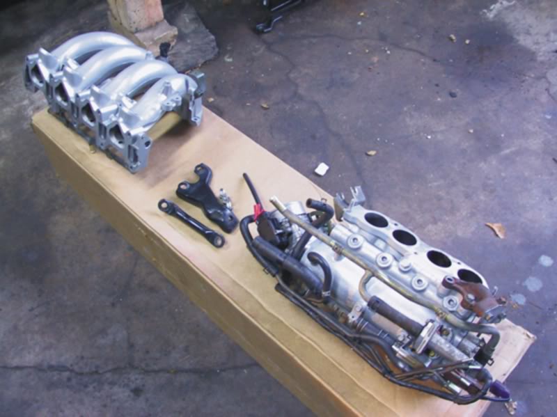
Disconnect the TPS harness and turn the idle adj. screw on the IAA to get the car to idle at 650 rpm. Reconnect the TPS harness and your beloved should purr at 700 or so rpm. (The Factory manual gives a +/- tolerance of 50 rpm.) The IAA is at the back of the intake manifold. You can see it standing over the right (passenger side for N.A.) fender and looking at the funky device with the dime size recess for the adj. screw.