By: Tangalora
———————————————————————–
SUMMARY: 90-93 Q45 chain guide repair (hints, suggestions, procedures):
———————————————————————–
Formulate a basic overview understanding of the situation at hand:
The whole chain is under tension; but we use tension & slack terminology.
The crankshaft pulls on the straight leg of the chain (the tension side).
Then (terminologically) the curved leg is “pushed” (i.e., the slack side).
The guides that were redesigned are the tension-side (straight) guides.
A new plastic tension guide sits on top of a new metal tension guide.
These two guides replace one guide (using longer bolts than original).
Light blue-gray RTV around the timing cover & oil pan is likely factory.
Red RTV would most likely indicate the cover was removed at one point.
The passenger side slack guide can be viewed by removing an engine porthole.
The slack-side (curved) guides don’t generally fail & were not redesigned.
The guides on the driver’s side are those that most often fail.
So, that would make the driver side tension guide the main failure item.
The original design used 2 guides per chain (slack-side & tension-side).
The new design uses three guides per chain (2 for 1 on the tension guide).
The slack-side guides were metal originally so new is almost identical.
The straight leg has enough tension it almost doesn’t need a guide.
Even if the tension guide fails, the engine may run fine for a long while.
The plastic pieces may wedge between chain and sprocket.
The timing cover may crack (leaking oil profusely).
The chain can break.
The chain can skip a tooth (or two or three).
The main danger is a chain jumping a tooth causing valve timing changes.
Each cam gear tooth is 10 degrees (each crank gear tooth is 20 degrees).
One crank tooth or 2 cam teeth is the ragged edge of exhaust valve contact.
The second danger is pieces lodging under the chain (perhaps breaking it).
Chain guide slop may also cause engine-cover oil-chain “ears” to break off.
That loose “ear” lodges in the oil pump sprocket & cracks the timing cover.
Broken pieces that fall into the oil pan are also a potential problem.
Large pieces (which grind ever smaller) may clog (starve) the oil pickup.
Smaller pieces (grinding ever smaller) may score the oil pump vanes.
There are 2 oil chain guides, but 1 wears faster than the other.
The slack-side oil pump guide doesn’t have a tensioner.
It’s just set in place and has to be manually adjusted (i.e., replaced).
Generally you do not have to replace the timing chains.
If you replace timing chains, it will take twice as long to do the job.
If you replace timing chains, the valve covers will have to come off.
The toughest chainguide step is R&R of the 270 ftlb crankshaft-pulley bolt.
Do NOT put a chain wrench on the pulley & then tap the starter switch.
You may put a wrench on the bolt resting on something solid & tap the starter.
Byron at T3 apparently also takes the pulley off the power steering pump.
Most replace the oil pump but there isn’t much evidence to show it’s needed. It would be interesting to test oil pressure before & after oilpan cleanup.
———————————————————–
Read how to perform the job based on others’ experience:
———————————————————–
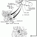
Factory Shop Manual, Engine Mechanical section:
Note: I could barely understand the FSM so correct as needed.
———————————————————–
Photographic summary of a chain guide & oil pan replacement:
http://www.q45.org/guidereplacement.html
(www.q45.org/guidereplacement.html)
http://forums.nicoclub.com/zerothread?id=77266
———————————————————–
Photo of tension side guides and slack side guides:
http://forums.nicoclub.com/zerothread?id=53660
(forums.nicoclub.com/zerothread?id=53660)
http://forums.nicoclub.com/zerothread?id=53660
(forums.nicoclub.com/zerothread?id=53660)
———————————————————–
Timing chain parts list:
http://forums.nicoclub.com/zerothread?id=15226
(forums.nicoclub.com/zerothread?id=15226)
http://forums.nicoclub.com/zerothread?id=13851
(forums.nicoclub.com/zerothread?id=13851)
———————————————————–
Checking chain guides:
http://forums.nicoclub.com/zerothread?id=7058
(forums.nicoclub.com/zerothread?id=7058)
http://forums.nicoclub.com/zerothread?id=12551
(forums.nicoclub.com/zerothread?id=12551)
———————————————————–
Replacing chain guides:
http://forums.nicoclub.com/zerothread?id=15861
(forums.nicoclub.com/zerothread?id=15861)
http://forums.nicoclub.com/zerothread?id=48852
(forums.nicoclub.com/zerothread?id=48852)
———————————————————–
Supporting the engine & tension-side chain guide information:
http://forums.nicoclub.com/zerothread?id=27044
(forums.nicoclub.com/zerothread?id=27044)
http://forums.nicoclub.com/zerothread?id=92067
(forums.nicoclub.com/zerothread?id=92067)
———————————————————–
Aligning marks for timing chain guide replacement:
http://forums.nicoclub.com/zerothread?id=71463
(forums.nicoclub.com/zerothread?id=71463)
http://forums.nicoclub.com/zerothread?id=710
(forums.nicoclub.com/zerothread?id=710)
———————————————————–
Checking for new chain guides:
http://forums.nicoclub.com/zerothread?id=15648
(forums.nicoclub.com/zerothread?id=15648)
http://forums.nicoclub.com/zerothread?id=12941
(forums.nicoclub.com/zerothread?id=12941)
———————————————————–
Chain guide replacement hints:
http://forums.nicoclub.com/zerothread?id=26454
(forums.nicoclub.com/zerothread?id=26454)
http://forums.nicoclub.com/zerothread?id=28462
(forums.nicoclub.com/zerothread?id=28462)
———————————————————–
Chain guide noise & broken timing chain cover debug steps:
http://forums.nicoclub.com/zerothread?id=16281
(forums.nicoclub.com/zerothread?id=16281)
http://forums.nicoclub.com/zerothread?id=46708
(forums.nicoclub.com/zerothread?id=46708)
———————————————————–
Obtain requisite parts from Joe of Scottsdale Infiniti or elsewhere:
http://www.EverythingNissan.com 888-216-5328
– 1x 13510-60U00 – front cover seal
– 2x 13270-60U00 – valve cover gaskets (if valve cover is removed)
– 4x 11051-60U04 – cam end seals (if the valve cover is removed)
– 1x 13091-60U01 – guide (tension RH)
– 1x 13091-60U11 – guide (tension LH)
– 1x 13070-60U03 – chain tensioner (RH)
– 1x 13070-60U12 – chain tensioner (LH)
– 2x 13085-60U01 – chain guide (tensioner guide?)
– 2x 13085-60U11 – chain guide
– 2x 13094-60U00 – guide bolts
– 2x 01121-04711 – guide bolts
– 4x 13075-60U02 – tensioner bolts
– 1x 13079-60U01 – tensioner gasket (LH)
– 1x 15041-60U00 – oil pump chain (highly recommended)
– 1x 15073-60U00 – oil pump chain guide
– 1x 15073-60U10 – oil pump chain guide
– 1x 15072-60U00 – bracket oil pump
– 1x 15044-60U00 – crank/oil sprocket
– 1x 15043-60U00 – crank/timing sprocket
– 2x 13021-60U00 – crank/cam sprockets (if warranted)
– 2x 13028-60U00 – timing chains (if warranted)
———————————————————————–
Line up the necessary shop tools:
– Garage tools (jack/stands or ramps, creeper, etc)
– Common metric sockets (8, 10, 12, 14, 15, 17, 19mm)
– You will use the 10mm the most by far so have a few types on hand.
– Large crank bolt socket (30 or 31mm)
– Ratchets and 10 mm wrenches.
– 18″ breaker bar and an extension pipe.
– A 300 ft-lb torque wrench (maybe).
– A large puller (Sears has them for about $30)
– A 5mm allen socket (do not use an allen wrench); this is CRITICAL.
– A chain wrench long enough to wrap around the main pulley.
– That chain wrench must have a 3-foot handle (or a 3-foot pipe)
– An old ribbed belt sufficient to wrap around the crank pulley (to act as a buffer between the crank pulley and the chain wrench, very optional).
– Other common shop tools–pliers, vise grips, magnetic tool pickups, etc.
– RTV (1 tube of Permatex Blue will be plenty, however Nissan Genuine RTV is included in the kit from Joe).
– Feeler gauges (1mm, 0.04 inches) for chain-to-guide distance.
———————————————————————–
Overview of chain guide replacement steps (no chains = 10 hours):
– Inspect lower valve cover abutment with engine for RTV color
– Or pull the front-most oil pan bolt to check the RTV in the bolt hole.
– If it’s light gray/blue, then it’s most likely still factory sealed.
– Red RTV (most common) is not factory (according to most accounts).
– This isn’t definitive; but it’s a circumstantial hint nonetheless.
– Remove all plastic trim pieces to expose radiator and cover.
– Drain coolant and remove radiator.
– Remove all belts.
– Remove all belt tensioners.
– Remove metal bracket on PS fluid pump covering front cover.
– Remove coolant hose running across front cover.
– Align the pulley to TDC (this is the last timing mark on the crank pulley, however the crank pulley is notched with a key so this is not 100% critical).
– Remove crank pulley main bolt with a wrench on the nut.
Remove crankshaft bolt:
– Tools = 30mm socket, 22″ chain/strap wrench, 18″ breaker & 30″ cheater bar
– Wrap a 20 inch protective strip of tire inner tube (or old ribbed belt) around the pulley
– Cinch the chain or strap wrench around the pulley (any location is OK)
– Turn the bolt counter-clockwise until the chain wrench wedges somewhere
– Check that the chain wrench wedged somewhere safe & solid
– Easily twist the bolt off using leverage (it will not take much effort)
– Actual time should be less than 15 minutes from start to finish
Remove crankshaft pulley:
– One assumption is the radiator has already been removed
– Tools = 30 mm socket, 24″ ratchet, 30″ cheater pipe
– Replace crankshaft bolt and place the 30mm socket on the bolt
– Twist the engine CLOCKWISE (to set #1 piston at compression TDC)
– Line up the CAS pointer to 270 degrees (facing engine) to set #1 compression
– Line up the left-most pulley notch with the timing-cover dowel to set #1 TDC
– Remove the crankshaft bolt without disturbing from #1 compression TDC
– With hands, manually tweak back to #1 compression TDC (if necessary)
– REMOVE the fat washer & replace the bolt loosly on the crankshaft
– Make sure only a few threads are engaged & that the washer is off!
– Tools = Sears 2-jaw puller #46903) or equivalent, 3/4 inch box wrench
– With a helper, position two puller jaws on the third lip of the pulley
– Place a 3/4″ box wrench on the puller shaft & twist clockwise
– Easily twist the pulley off using leverage (it will not take much effort)
– Actual time should be less than 15 minutes from start to finish
– Remove the front lower timing chain cover screws.
– Note there four oil pan bolts holding the lower timing chain cover.
– Note the upper timing chain covers may remain on the engine.
– Remove the lower front cover.
– Note the 6 different lengths and 32 bolt holes (keep track).
– Pry at the bottom corner of the cover, near the alternator
– Also pry just below the water pump.
– May need to remove the pump (5 bolts and RTV) to get to pry point.
– Try to pry/pull as evenly as possible.
– Don’t damage the solid gasket between lower & upper timing covers.
– Immediately after removing the cover, block the oil pan with towels.
– Inspect all timing chains for cracks or excessive wear indications.
– Locate the TDC dimple below a tooth in the crank sprocket.
– Just above that dimpled tooth should be a timing chain GOLD LINK.
– Remove the oil pump chain, guide and sprocket (which is not keyed).
– Note the oil pump crankshaft sproket has a key cut.
– This oil pump crank sprocket keyway isn’t used to hold it in place.
– Compression/friction of the 270 foot pound crankshaft bolt holds it.
– This oil pump sprocket keyway is there only to put it on the crankshaft.
– Cinch timing chains tightly to prevent jumping a sprocket tooth.
– This is the most critical step (most folks use tie wraps)
– Remove the old chain guides (don’t let the chains loosen).
– Re-cinch chains, if needed, to be safe (do we use a 1mm feeler gauge?).
– Use a 5mm allen socket to remove the old tensioners (very tight)
– Install new tensioners and guides (don’t use a 5mm allen wrench)
– Measure with a feeler gauge 1mm distance between upper guides & chain.
– Make sure there is no gunk clogging the tensioner oil ports.
– Use “BG Quick Clean for Engines” (if necessary) to unclog HLA passages.
– Try to fish out any pieces left in the oil pan (or vacuum them out).
– Install new oil pump chain, guide and sprocket.
– Turn the crankshaft slowly by hand before putting covers on.
– If anything binds, now is the time to find out.
– Clean the mating surfaces of the cover and degrease
– Don’t bend the solid gasket above the cover as you install the cover.
– Note there is no RTV between the timing cover and its solid gasket.
– Apply fresh RTV and install cover with all bolts.
– Torque all cover bolt to spec where possible (see FSM).
– Torque the crankshaft pulley bolt to 270 foot pounds.
– 90 lbs of force on a 3-ft bar will do if you don’t have a torque wrench.
– Install everything in the reverse order of removal
– Fill up coolant
– Fill up the oil
– Turn main pully two full turns to spread oil around the engine.
– You’ll feel & hear the compresson cycles; hopefully nothing else.
– Torque up the main bolt to 270 ft-lbs before replacing the belts.
– Two strong guys are probably best for this step.
– Pull the fuel pump fuse and crank the engine to spread some more oil.
– Replace the fuel pump fuse.
– Crank engine & turn off imediately 5 or 10 [sometimes 20] times.
– It may sound like the engine is going to explode for a minute.
– HLA & tensioners need to bleed air admitted when you changed them.
– The noise should suddenly go away after a few minutes running.
– Run [multiple] warm/hot power balances
– Make sure every cylinder drop is no more than 25 rpm variance.
– If you have not dropped the oil pan, run an oil pressure check.
– This might tell you if the oil pickup is clogged with guide debris.


