Overview
A 240sx 5-speed swap is arguably the most worthwhile modification you can make to your auto 240sx, and should also be the first if you plan on anything other than daily commuting.
Difficulty: ****
Time: 8-12 hours
Cost: $200-$500
Tools:
– FSM
– Torque wrench
– Socket set
– Floor jack
– Fluid catch pans and spill mats
– Phillips head driver
Materials:
– 5-speed transmission
– 5-speed crossmember
– 5-speed driveshaft
– Flywheel and MT bolts (marked “MT”)
– Clutch and pressure plate
– Release bearing
– Master and slave cylinders
– Hardlines and rubber line from master to slave cyl.
– Clutch pedal
– Brake pedal (optional)
– Boots and brackets for shifter assembly
– Lower wire harness
Procedure:
1. Remove the finisher plate and center console.
2. Drain the ATF fluid. This will reduce the mess you make considerably.
3. Disconnect the driveshaft at the differential by removing the 4x 14mm bolts and drop the end. Remove the carrier bearing as well.
4. Remove the ATF cooling lines. Theres one on each side feeding from your radiator, they connect at the bottom.
5. Support the rear of the transmission and remove the 4x 17mm bolts for the crossmember. Remove the cotter pin on the linkage and then the shifter. Unscrew the shift lever and remove the metal plate underneath.
6. Lower the rear of the transmission to gain access to the bellhousing bolts.
7. Remove the starter. (2x 14mm bolts)
8. Remove the remaining bellhousing bolts and the dust cover to gain access to the torque converter bolt. At this time, you should be able to slide the transmission back out of the way if you have it supported by a jack.
9. Remove the 6x 19mm flywheel bolts.
10. Remove the a/t adapter bearing, which extends past the end of the crankshaft. This will be difficult.
11. Install the pilot bearing.
12. Install the manual adapter plate to the bellhousing.
13. Install the flywheel and torque the bolts per the FSM.
14. Using the clutch alignment tool, install the clutch to the flywheel, then install the pressure plate. Remove the alignment tool. Drive the release bearing off the retainer and install the new bearing. Reinstall the lever arm and springs.
15a. Disconnect the brake lines from the MC so you can work the brake booster back a little to get the pedal out. Worm your way up under your dash and remove the green box up where the clutch pedal should be. That’s the shift lock control unit. Just uplug it for now. Now, remove the cotter pin holding the brake pedal to the brake MC fork. Best way is to rotate it till the loop faces down, and take a curved instrument like a pick and pull it out. Now, you can undo the four bolts on the firewall and then the one bolt at the top of the brake pedal bracket. Disconnect the two plugs and worm the pedal out. Now, take your new shiny (or rusty depending on where you got your pedal) brake pedal and put it up on the four studs of the brake booster. Thread the nuts back on, put the top bolt back in, tighten the nuts down, and then finally tighten the top nut down. Reinstall the fork pin and it’s cotter pin. Fun.
15b. Cut the brake pedal in half to accomodate the clutch pedal.
16. Pull back the carpet, find the rubber mat and remove the cutout for the master cylinder to go through.There will be no hole through the metal, you will see the mounting locations from inside the car only (this looks like they just used a different firewall for the outside with no holes on the outside panel.Drill two holes for the studs, then drill a hole right in the center for the master cylinder to guide a hole saw. Measure your master cylinder for the correct size. Mount the master cylinder to the pedal assembly.
17. Metal line from master cylinder across the engine bay along the top of the fire wall and down with the rest of the brake lines down to the bleeder tube assembly mounted to the inside of the passenger side “frame rail”.Install the bracket for the rubber line which goes from the metal line to the slave cylinder.
18. Remove the shifter from the transmission – Remove rubber boot, there is a snap ring that holds the shifter in place.Make sure all sensors are installed in the transmission at this point. Speed Sensor, Rotation sensor, Reverse light switch, Neutral position switch, 5th gear sensor. Jack the front of the motor up to tip it on an angle. I found it easiest to have two people on this part, one in the front and one on the tail shaft. Lift the transmission up and turn it so the bump in the bellhousing for the starter is pointing towards the ground. Get the input shaft lined up and slide the transmission in. Rotate the transmission into position and fasten one bolt to hold it. Support the tailshaft. Put in the rest of the bolts and nuts which mount the transmission.Hook up the slave cylinder.
19. Bleed the lines. Watch the fluid level in the reservoir, it drops fast when bleeding the clutch lines. Bleed the slave cylinder first then the bleeder lines.
20. Slide the front half of the driveshaft on the output shaft of the transmission. Bolt up the center coupling to the body 2-17mm.Bolt up the 4 bolts that secure the drive shaft to the differential. Make sure the yellow line on the driveshaft aligns with the yellow line on the differential. Install the body floor pan brace.Put in the correct amount of 75W-90 GL through the shifter hole (2.5L I believe).Install the shifter (Snap ring), rubber boot, upper rubber boot & plate.Install console, and finisher plate with the upper leather shift boot. Install shift knob.
21. Now, to make your reverse lights work, your top work (convertible), and to get the car to start.
Find the passenger side fuse box. If you look at it, it will have 4 plugs hanging off of it. 3 large plugs, and a small 2 wire plug (it’s not visible in the picture except by the two wires connected by the yellow splice).

The small 2 wire plug is the park neutral switch. To make the car start, you’ll have to jumper those. The easiest way is to cannibalize the plug off the AT tranny harness. Then you can just connect the two wires together with a splice and plug it back into the chassis plug.
Next is to make your park and reverse lights work.
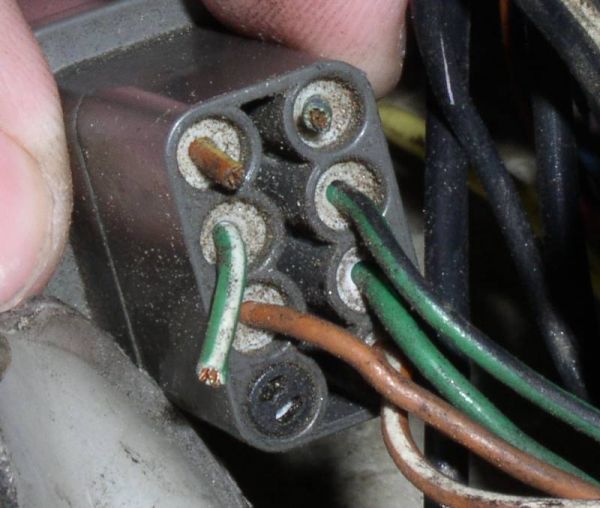
The middle plug of the three larger plugs is called the inhibitor switch.

(Back of the inhibitor switch)
The way the wiring of this plug works is like so: the green/blue wire is a constant voltage wire, and all the other wires run to gear sensors (park, neutral, reverse, 1st, etc).
Wire colors needed for operation:
Green/blue to complete the circuit
Brown/yellow for park
Green/white for reverse

If you look at how I’ve done my wiring, I have directly connected the brown/yellow and green/blue wires. This causes the car to believe it’s in Park at all times, allowing the top to function. Then I spliced wiring into the green/blue line (that is what the blue box is for. It allows a wire to tap into another wire without having to cut it or solder it). The new wire was ran to one of the reverse plug wires. Then I ran a wire from the green/white wire. These wires were ran to the reverse sensor. When the shifter is put in reverse, the sensor will complete the circuit and turn the reverse lights on.
***NOTE: If you disconnected your brake lines to install the new brake pedal, bleed the lines!***


