Nissan D21 2wd Hardbody Suspension Upgrade Part 1: Torsion Bars and Front Bushings
I had been having less than stellar performance and not-so-right alignment pretty much since I bought my truck. I replaced all the steering components two years ago. I have upgraded the shocks and have added poly sway bar bushings. I have added a rear sway bar and plus-sized my rolling stock from 195/75r14 (14×6) to 205/60r15(15×7). The handling is decent. Sumitomo HTR tires are fun. The rear sway bar does a good job planting the rear end and shedding 50lbs by removing the rear bumper has really made the handling come alive.
So back to the story: 16 year old bushings can be blamed for the trouble I am having keeping the truck aligned. I have the truck aligned every Spring whether it needs it or not but last year I had to go back 3 times to have it “fine tuned”…and it’s still squirrelly and chewing up tires on the outside edge. The suspension has settled over the years so even when it’s ‘in spec’ on the rack it’s still not correct when on the road. It’s time to update if this sounds familiar! Here’s a guide to rebuilding and upgrading the front suspension of your 2wd Nissan D21 Hardbody Pickup.
On the list: replacing every bushing, every ball joint, changing bump stops, replacing the OEM torsion bars with Sway-A-Way which are close to 4mm thicker and finally lowering the front by about 2”. New nuts and bolts too, as much stainless as I could source.
First here are some pictures of the parts we will be replacing.
Upgrading OEM torsion bars to Sway-A-Way bars..

OEM vs. Sway-a-Way

Thickness of OEM bar.

Thickness of Sway-a-Way bar.

New Hardware.
Start by lifting the truck and placing it on a set of suitable jack stands and remove the front tires. I marked the original positions of the torsion bar adjusting bolts for reference, a white paint pen works well for this. Once they are marked it’s time to loosen and remove the adjuster lock nuts. PB blaster is your friend here.
Warning!: Suspension torsion bars are under stress and can contain a destructive amount of potential energy, be safe and use protective gear at all times while adjusting the torsion bars.
Once the tension is removed from the bars (mark on the frame the angle of the anchors for future reference) slide back the rubber boots on the bars themselves to expose the snap ring retainers. I used two flat-head screw drivers to tap them out of the grooves. Depending on how rusty your D21 is you might have your first fight at this stage. The anchors need to slide off the end of the torsion bars now. You might get lucky and they just slide right off or they may be really stuck from years of road grime and require persuasion. Mine only required a couple hits from a dead blow hammer to loosen up…got to love Florida trucks!
You will need to remove the anchors mounted to the lower control arms (2 bolts with nuts…one of which can’t be slid out of its hole until the lower control arm is off.). This helped because my bars were stuck. Once I remove the mounts I could tap them off the bars.

What I call the ‘sun bolt’ exposed.
Now if you are only looking to replace the torsion bars and nothing more you can just reverse the process starting here. I took things many steps further because I treated this project as a restoration. If you are reinstalling the bars at this point I can not stress lubing the bar splines enough. No lube means you will eventually get articulation moans and groans as metal to metal contact happens at these points. I used never-seize and a generous amount too. Keep reading if you doing a full rebuild.
Next we need to take apart the front end. This includes removing upper and lower control arms, the knuckles, tension rods, steering arms and sway bar links. Removal of the upper arm is easy and starts by separating the upper ball joint from the knuckle (ONLY if you plan to replace the upper ball joint otherwise just unbolt from upper arm and leave attached to knuckle). Take a look at this breakdown, we are going to be removing 95% of the parts listed.

Break down of 1995 Nissan D21 2wd Truck Front Axle.
When all is said and done this is what things are going to look like.

Everything removed from Front Axle.
I upgraded the bound bumpers to Daystar progressive poly bump stops because the truck was going to be lowered from the factory height. Installation is simple and only requires I ream the hole out slightly.
Caution: You will want to keep track of the shims that are placed behind the upper control arm spindle as these affect both camber and caster. I did not reinstall these because I wanted more negative camber.

Daystar Progressive Poly Bump Stop Installed (Hole needs slight reaming).

Upper Control Arm Removed with Spindle still attached.
Here is where the real fight begins and frankly the worst part of the entire job. Some say to burn the lower bushings out but I was not thrilled with that option since a flame has no choice but to start burning the starter motor just above the bushing. Also the rubbery mess I have seen in other threads might work for the hot-rodder who doesn’t care about what on-lookers can’t see behind the scenes but I wanted the cleanest install I could get.
Caution: If you chose to burn the bushings out be prepared for toxic and odor-filled fumes. Also realize the potential danger of a fire which could have catastrophic results. I advise against using flames in this situation. A few extra minutes doing it the hard way will yield better, safer and cleaner results.
So here we are, the lower control arm bushing. No it won’t just press out unless you have one hell of a press at your disposal. Energy Suspension bushings require we reuse the outer shells of the OEM bushings which means we have to clean out all the guts of the OEM bushings while leaving the outer shells in place. I started by drilling out the bushing material from both sides. Clear out as much rubber as you can. Once you have completed that now it’s time to press out the center sleeve. Using a homemade press from parts I got from the hardware store I forced the center sleeve out leaving an ugly mass of rubber and the outer shells behind.

Homemade Press

Picture of Lower Control Arm sleeve on the right. Upper Control Arm Bushings on left.

Control Arm Bushing Residue. A few suggest using flames to burn the residue out but I opted to do things by hand instead for safety reasons.
This might take a while but the results are worth it. A wire brush attached to a drill does a good job cleaning out the residual rubber. Leaving you with a honed-like finish.

Drill and Wire Brush setup.

Lower Control Arm Bushing Shell cleaned.
Next we lube up and install the Energy Suspension bushings into the OEM outer bushing shells. Lots of lube here, this where squeaks come from if the material is installed dry.

Here we see the new bushing and sleeve installed.
Time for a beer!
While I had the lower control arms out I took some time to clean them up, have new Moog ball joints installed and painted them up with Rustoleum paint. Same for the uppers as well.

Reconditioned OEM upper and lower Control Arms.
So I was tired of lying on my back under the truck and decided to do some more of the easier work. The upper control arms are not half as bad as what we just got through. Start by taking the nuts off the ends of the spindle. You will once again be drilling though rubber bushing material but this time you have to be careful of how deep you drill because there are washers on the insides of the spindle that no local hardware shop on Earth will carry, DEALER ONLY!!! Ask me how I know this.
Once again you will want to lube the bushing up good before installing them, an ounce of prevention is worth a pound of cure, same holds true here.

Upper arm ready for installation.
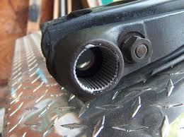
Torsion bar anchor reinstalled on lower control arm.
Time to reinstall the lower control arm. The trick here is to articulate the arm through its entire range of motion checking for binding and noise. Noise means more lube is needed. Do not torque the lower control arm mounting sun-bolt yet, only tighten it a little. A block of 2×4 about 8-12” long is very helpful in holding up the lower control arm when things need to be lined up.

This picture shows both upper and lower control arms installed. Note block of 2×4 holding up lower control arm.

Torsion bar anchor mount in position.

Front of lower control arm.
From here it’s only a matter of putting things back together. The knuckle will be put back in position, torque the ball joint nuts and install new cotterpins. Steering linkage will be reinstalled and torqued to proper spec. Sway bar links and related need to be reinstalled. Strongly recommended to upgrade sway bar links to Energy Suspension to take advantage of a full poly front end.

RF Corner.

RF corner going back together.
Reinstalling torsion bars. LUBE LUBE LUBE, can’t say it enough. The Sway-a-Way bars slid right into position with no issues.
Caution: Torsion bars are directional left and right. Failure to follow this rule WILL result in torsion bar failure.
I used all new hardware from Nissan as I was treating this project as a restoration. You can reuse most hardware but I would not reuse the snap rings, age seems to weather even Florida truck hardware. Hopefully you remembered to mark the angles of the rear torsion anchors during disassembly as this will make indexing the bars much easier.

Sway-a-Way torsion bar installed.


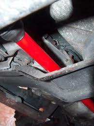
OEM rubber boots will need to be slightly modified to compensate for the thicker torsion bars. If you are running OEM bars this will not be an issue.
Using the FSM page I included above torque all the components to spec saving the control arm bushings for last. You will only want to torque the control arm bushings once the truck is back on the ground. Make any final system checks and adjust if needed. Check steering, check for play and check for leaks and squeaks. You will need to readjust ride height. If you measured ahead of time and want the same height as before you can adjust the torsion bars accordingly. Obviously if you are lowering the truck you will want to take measurements on a flat surface and make adjustments there. There is no science to how many turns of the bolts and the resultant height change (some will say there is but there is no way to say it’s the same for every truck), measure each time.
Take for a test drive giving everything a chance to break in, don’t abuse it right off the bat. The truck will settle after a few days so I suggest you put a pair of crappy tires on the front to drive on before you get an alignment. This will allow the truck to settle and allow you time to make sure the project doesn’t need more attention.
Remember any questions you may have can be asked in the comments thread: Nissan Hardbody Suspension Upgrade Discussion
Also, make sure to join us in the Nissan Truck Forums.
Thanks, and happy Truckin’!!
Sources:
Poly Performance Inc.
Energy Suspension
Sway A Way
Nissan OEM Parts
Daystar Suspension
Moog Suspension Components
