Article Series
- Restoring a 1968 Datsun 510 Sedan - Meet "Betty"
- Restoring a 1968 Datsun 510 Sedan - Front Suspension
- Restoring a 1968 Datsun 510 Sedan - Rear Suspension
- Restoring a 1968 Datsun 510 Sedan - Differential and Rear Brakes
- Restoring a 1968 Datsun 510 Sedan - Wiring with a universal harness
- Restoring a 1968 Datsun 510 Sedan - Engine install, door hinges and bumpers!
- Restoring a 1968 Datsun 510 Sedan - Weatherstrip and window squeegies
- Restoring a 1968 Datsun 510 Sedan - Part 8 - Seats and Wiring
- Restoring a 1968 Datsun 510 Sedan - Part 9 - Lighting
- Restoring a 1968 Datsun 510 Sedan - Part 10 - Radiator and cooling system
- Restoring a 1968 Datsun 510 Sedan - Part 17 - NICOclub
Getting close to the end of a restoration project is an interesting time… For some people, it’s super-exciting, and they tend to rush things towards the end, just to hurry up and get it out on the road. For others, like me, it’s bittersweet.
Once the project is this far along, it’s too late to go back and redo major things, but it’s also a time when you find all the errors, mistakes, and failures. So, my excitement is tempered by the knowledge that the next month or so is going to be stressful and frustrating – as I find all the things that don’t quite work perfectly, parts that don’t play nice together, or worst yet, finding out the car doesn’t do exactly what I wanted it to do.
SO, I approach the latter stages of a project with a little more care, and trepidation, than most folks. How about we get a hood on this gal and get her ready to fire up for the first time?
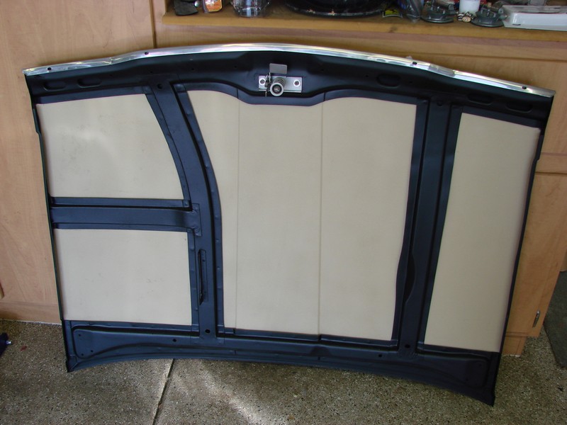
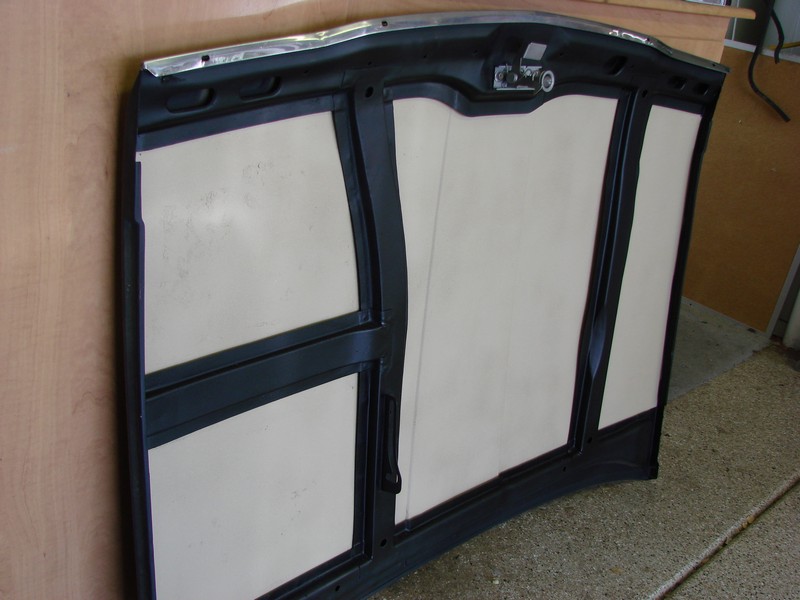
The hood on our 510 was super-sexy on the top, but the underside still looked like the “before” engine bay pictures. Why someone would dump months of bodywork and paint into a car, and not refinish the underside of the hood, is beyond my comprehension – but we’re gonna work with it.
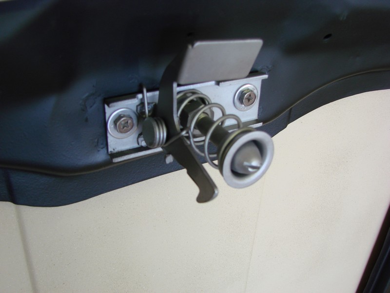
Because the metal between the bracing is thin, we want the hood to be a little more “substantial” – but putting sound deadening on a classic hood just doesn’t look right. So, let’s go back to our old friend, truck bedliner! I wanted the hood to have a little character – let’s face it – there’s a lot of satin black on this car, and it needed something to break up the darkness. I chose a desert tan material for the hood, which will contrast nicely with the hood bracing, and reflect a little more light down onto our L20b in the bay. A freshly bead-blasted latch and clean hardware finished it off nicely – don’t you think?
Once the hood was finished, Doc and I spent a little time talking with the guys over at Pierce Manifolds. They’re a wealth of knowledge for all things related to carburetion and linkages, and they’ve helped me out several times in the past. There were several problems with the setup you saw in the last episode, such as:
The stamped steel arms we got from Redline are crap. Sorry, guys, but there’s just no other way to describe it. They’re far from precision, and they don’t really tighten on a linkage rod very well due to their design. They bend easily, and after a few adjustments, they simply wouldn’t clamp the drive rod consistently under hard throttle opening / closing. This throws the carbs out of sync, and just isn’t acceptable.
The linkage rod thickness (3/8″) is too thin to resist bending. The whole idea of using a bellcrank and a linkage rod is to translate the movement of the pedal into a left-right motion, which is then translated into rotational force on the rod. In our case, the bellcrank was placing lateral pressure on the end of the rod and flexing it ever-so-slightly, which caused binding and uneven application of rotational motion to the carb linkages. Not gonna work.
Lastly, the entire linkage was mounted to the manifold via the Heim joints. The problem here is that any time we had to make an adjustment that required removing the carbs, the entire linkage assembly had to be taken apart. This wears the threads in the soft aluminum manifold, and eventually will require a helicoil insert. PLUS, it means we have to re-adjust ALL of the linkage points again, which is a colossal pain in the ass. No thanks.
TO address this, we’re going to need to get creative. Doc and I decided to make the entire linkage removable as ONE component, which meant mounting it on its own pedestal. A chunk of aluminum stock was drilled to match the mounting holes in the manifold, and mocked up to serve as a “stand” for the linkage assembly. Then, I radiused the ends (for appearance), gave it a nice brushed finish with some 400-grit paper, and clear-coated it for durability.
Next, we ordered a 5/8″ T-316 (marine-grade) stainless steel rod, which is significantly stronger and more resistant to bending, than standard T-304 stainless, or the lower-grade stuff you find in local stores. It wasn’t cheap, but it will do the job perfectly AND it won’t mar or nick from tightening the throttle arms on it. I spent some time polishing it to a high-gloss finish, and ordered a new, larger set of Heim joints from Grainger to fit it.
Finally, we added a set of billet aluminum throttle arms from our friends at Pierce Manifolds. These things are stiff, beefy, and have a properly-designed clamping mechanism that won’t loosen up or slip on the throttle rod. Putting it all together on the pedestal, which will be removable as one complete piece, left me thinking we should have done it this way in the first place!
I actually found a set of air horns for some Mikuni carbs in one of the boxes of stuff I bought at the beginning of the project, so I refinished them with a polishing wheel and attached them for the finishing touch. I think it turned out pretty nice.
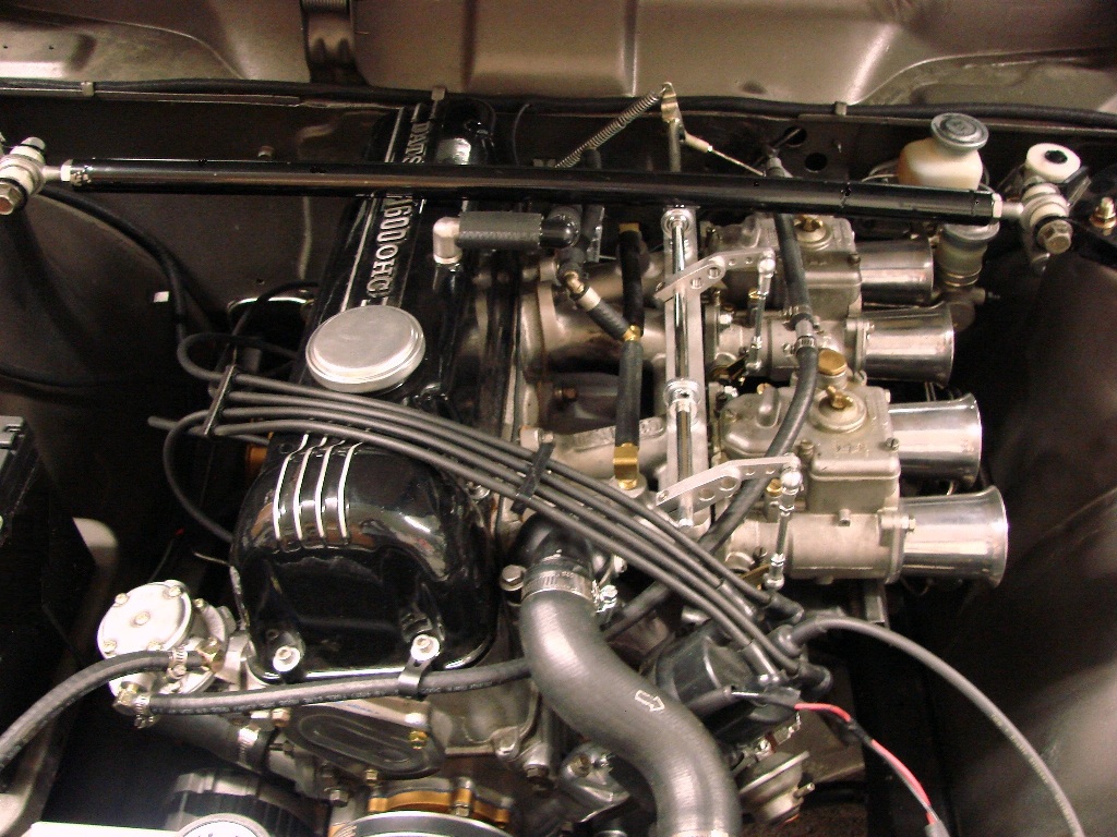
In the picture above, you’ll also notice the strut tower brace. There’s maybe one or two companies making a brace for the 510, and some will say it’s not really necessary. However… read on.
While we were at it, I found a set of “feet” from an abandoned strut tower brace project that just happened to match the strut tower pattern on the 510. (They’re either 240sx or Honda, I can’t recall. Maybe someone else can help?) I had a piece of heavy-gauge hollow steel bar stock with threaded ends (no idea what that was for, but it was in my garage!), so I asked Jason to section and sleeve it to the proper length. I then ordered another set of Heim joints from Grainger that threaded into the ends, and used some leftover nylon spacers and seat belt bolts to finish up the ends. It’s adjustable for preload tension, and it’s WAY more beefy than the aluminum crap that some retailers are selling. It’s not pretty, but it has a “all-business” look. PLUS, the price was right!
I’m thinking we should probably fire this thing up and try to get it rolling under its own power – Whatcha think? Let’s get it on! Project 510 – Part 13